Can we create the optimum wing first?

This is a dicussion, I am not claiming that the following is right.

I am not convinced that E-foils should use the same wing geometry that Kiteboards, Wakeboards or Surfboards use. In those three cases, the propelling force acts high above the board. This generates a moment that wants to push the nose down into the water. Therfore, the back wing is inverted and creates downward lift. This counteracts the moment generated by the Kite, Cable or Sail. Remember, they are acting on the exactly oposite end as the motor.

On an E-foil, the propulsion happens very close to the wing, the generated moment is much smaller here and in the opposite direction. So I belive that the back wing is not optimal. I saw a low of videos where the surfer has to lean forward a lot to keep the nose down. So the surfer is acting against the back wing which can only cause drag and wasted energy. The Wings should rather be like on an airplane and going both in the same direction.

Here is an uplifiting idea:

I think we could push the e-foils development much further if we could create the optimal wing first. An open source design would be amazing, so people could compare their results. Unfortunatley, I don´t know much about flow analysis. What are your thoughts?

7 Likes

Did you ever see an airplane?
You are just wrong!
The backwing is generating a downforce because of stability. If you have your center of gravity before the front wing, and the back wing pointing down, you got stability. It doesn’t matter if the medium is air or water or whatever. This is just mechanics. Google it there are many explanations.
Only military jets are flying instable, but the have a heck of flight controllers stabilize the jet. The can’t even fly straight without the help of the controllers.

Short story, either you get a stabilizing controller and servos at your wings, or better use the stable configuration

Of course, @Giga you are right but I do agree with @MaxMaker that there are different requirements for kitefoils than for efoils. Talking about stability you could for example get rid of the anhedral of the wings which of course looks cooler but strongly decreases lateral stability. For me as I also like to build my own wing the more interesting question is how to modulate it and what materials to use.

1 Like

As far as we all know liqiud force wing is able to do the job . Maybe some one has this wing and he is able to model it in 3d . To scan wing you can use even kinect from microsoft.

1 Like

its very easy to experiment with different wings very simply, the latest ones I built in a few days with high density foam than I simply hand sanded with a block and then glassed. There is a lot to be said for if it looks right … the rest was a cheap foil that works amazing. If any one needs high density foam drop me a message as I buy it in bulk so could probably so a better price than most. ! it may not have any flow analysis done on it but it certainly works a treat.

2Capture|666x500

1 Like

@charlieuk, hey. Good to see you here. I’m going to cut some HD foam wing sections and carbon wrap so I can do some experimenting. Can you guide me a bit on how much carbon to use? Ounces, layers, ? Many thanks

maybe laminated plywood, over a former with epoxy, I’ve seen a layer of fibreglass matting between each layer for added strength

it is good to think about the forces at had for sure, its interesting, it seems to be like a pendulum effect, would the propeller drive below the wing be worth a ponder, at least it would have clean water coming in, (if you ever drove a motorbike behind a truck, you hear the turbulence in your helmet, and only when you pass him out, it becomes smooth clean air again, id say waters the same)

If anyone is interested, i found a while back an excel spreadsheet to help designing foils. The result are very close to reality and will give you a good idea of the lift of a foil for a given speed

https://www.dropbox.com/s/gf6x7xn9ik2zrvf/lift.xls?dl=0

3 Likes

Nice but still someone have wing .stl file or step ? Fastest way for me is to print in 4- 5 pices and cover with fiber glass for test should work.

Yeah, why always use carbon? In my experience fibreglass is a better value alternative and easier to work with.

Carbon is a lot stiffer than fibreglass, therefore you can use less material to achieve the desired stiffness for the wing. It also results in a much lighter wing.

Sure but 10 times more expensive.

Could laminated thin plywood be an idea, if you think of the strength of a skateboard, and that’s only around 10mm thick,
carbon does sound nice though,but having the wing as sharp as a blade, is another safety concern

A lot of people have laminated 3mm ply to build the core, shaped it and then glassed it.
In terms of a skateboard, there is this guy that actually just used a skateboard deck: https://www.seabreeze.com.au/forums/Kitesurfing/General/DIY-hydrofoil-with-rubbish-and-an-angle-grinder
If you can get a deck that has no concave I think its almost a no-brainer as a starting point.

1 Like

yea, i seen that video over the summer, still deciding on the propeller at the minute, bought the 24" slingshot mast an base, the wing is another few stepping stones away :slight_smile:

I got the 30" mast and base, and then got a Unifoil (South African brand) Wing, Stab and fuselage (All carbon). I just have to mill an adapter for them and then its done.

1 Like

I have been getting to know the Heliciel Software, although the dialogs are mixed between French and English and the UI design is unusual, the program has the tools to apply to creating and estimating the optimum foil wing and propulsors. It is definitely increasing my understanding of the dynamics of the shapes.

In order to learn more about the design process, I am happy to enter some suggested foil dimensions and share the resulting lift and drag results here.

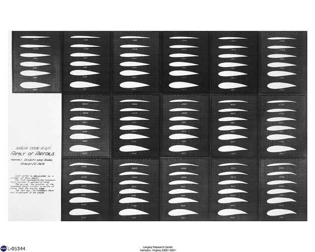
Here is how a foil is specified within the software, foil is selected, ocean water, 10 degrees C, the profile dimensions on this diagram page shown below are not to scale, they are schematic. You can also choose a profile from the database or input/import your own foil profile. Below is the image of some of the NACA profiles. Source here. Based on nothing whatsoever, I choose a NACA0010 that has a thickness of 10% of the chord length. Half wing length of 300mm, width at the root of 160mm and width at the tip of 80mm are entered. A design target of 10 meters per second is specified.

Curvature is specified in another dialog and left out for this first post.

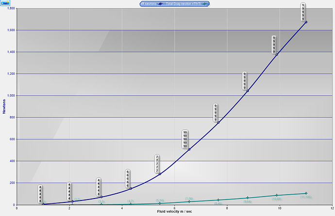
Figures shown are half of the total values as the program is only estimating one side. At 36KPH, this wing will have a lift of 2800 Newtons, a drag of 42 Newtons, and a calculated 1800 Watts to overcome the drag of the full wing.

Doing a further analysis, the program cruches away and returns this chart showing the lift and drag at various speeds. This chart would show 110 kilos of lift at under 7 kph, factoring in only the main wing. Drag numbers do not reflect the board, the mast, or the motor/propellor unit.

Obviously the variations are unlimited. The question becomes the desired speed in a hydrofoil to achieve a given amount of lift. 110 kilograms at 12 kph for example. Maybe we can have a discussion on the average speed to center the designs around? Lower aspect winger i.e. wider wings will provide more lift at low speed but more drag at higher speeds. Narrow wings, higher aspect, will achieve the required lift at a higher speed but will have less drag going fast. What speed is ideal to lift out of the water? What is an idea top speed?

If anyone can supply some existing wing measurements, such as overall width, chord width root and tip, chord thickness and a plan view photo, I can try to enter in the shape and see what the results are. As time permits.

5 Likes

Hello,
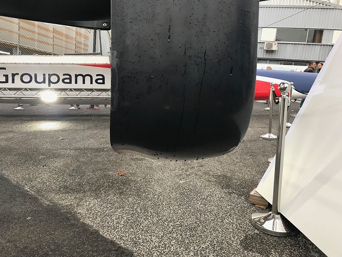
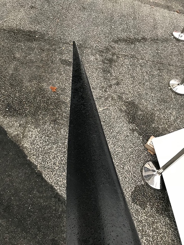
I have taken some photos of an AC50 foil, and it shows something like a NACA series 6 (the closest one I found is the NACA 63(2)-615) this profile has an advantage that could be useful for us. For example over a range of low attack angle, speed is transformed into lift without increasing the drag. @x-jets Would it be ok for you to do some simulations with this type of profiles?

Also, the chord of the tip was extremely narrow maybe 50mm

First test specs, NACA 632615 Half wing width 300mm, root chord 100mm tip chord 50mm shows structural warning at root in aluminum


2 Likes