Building an 18650 battery with individual cell fuse wires

Search my posts. Read up on understanding series and parallel battery connections, and read up on balance charging lithium batteries.

These batteries are very dangerous. You must learn all of these things before to start playing with them, before you try to build your own.

I have made several posts replying to other questions in the last month. This information should be a good start. But, please read enough to understand these things.

Any questions after learning this stuff, I’m happy to help.

:call_me_hand:

tell me please, how much time is spent on exercises using your hobby-charger, and where you bought the samsung18650? nkon?))

I purchased cells from IMR.

I run two icharger X8 chargers off one server power supply. It takes me 3hours to charge my 42a/hr 14s14p battery when fully depleted.

Details below.

:call_me_hand:

The icharger X8 I use can only charge up to 8s battery. So, my battery is made as two 7s batteries. This charger is more then enough to charge at maximum rate these cells can handle. So, if you have two chargers you could charge the 14s14p battery in two hours.

Samsung 30Q cells are 3.0ah capacity. They can be charged at a rate of 1.5ah safely if you want them to have a long life. So, that means 2 hour charge time if the fastest the battery can be charged.

The icharger X8 is a 1100 watt charger. So, if you have a 1100 watt power supply, then this charger could charge half the battery (7s14p) faster then the battery can handle. 1100w÷28v=39.3a and 39.3a÷14p=2.8a per cell. So, limit change to 1.5a per cell = 21a.

If you buy one icharger X8, you’ll have to charge one pack at a time. So 4 hour charge time. I bought two of the icharger X8. Then I don’t have to remember to come back and swap the charger over to the other battery.

But, I run both chargers off one power supply. So, the capacity of the power supply is the limiting factor.

My power supply is a HP 1000w server power supply. And I use 110v. So, 850 watt max output. 850÷28=30a. So with two chargers that’s 15a per charger. 15a÷14=1.07a per cell. So, this is a 3 hour charge time for the whole 14s14p pack.

:beers::call_me_hand:

4 Likes

Thanks for good big answer :call_me_hand:

1 Like

Working on my second battery.

The first battery design worked so good I’m basically doing the same thing on this build with just a few improvements.

Got the bus bars premade thx to one of my friends / build partners. Thx @Telejacket.

I got the battery sanded, fluxed, and tinned today. I hope to get this battery done this week.

Stay tuned for more updates.

:call_me_hand:

4 Likes

Here’s a post I made in another thread.

I learned the importance of fusing the balance lead wires.

Don’t burn the house down guys!

:call_me_hand:

2 Likes

Very nice work on the battery solution. I’ve read the whole thread at least once and parts of it 2 or 3 times in preparation for building something similar. Also the balanced fusing idea is great. I thought to decrease the complexity by putting some fuses in-line (but increase the wiring mess).

Some questions that I couldn’t understand after re-reading…

Can you clarify how you ran them in series in 1st or 2nd build? It appears you run the negative from the negative output of the 1st trolling motor connector into the lead for the 2nd trolling motor connector, then the negative from the 2nd motor into the ESC box. Hard to see from the picture.

image

What electronics do you have in the small waterproof cases? I’m confused as to what those are…

Did you hot glue the busbars (where the balancing fuses attach) to the battery spacers or how are they attached?

How did you waterproof the trolling motor connectors?

Many thanks - I’ll share my experience in building something similar as it comes together, which is soon, since I have all the parts on the way.

Hi.

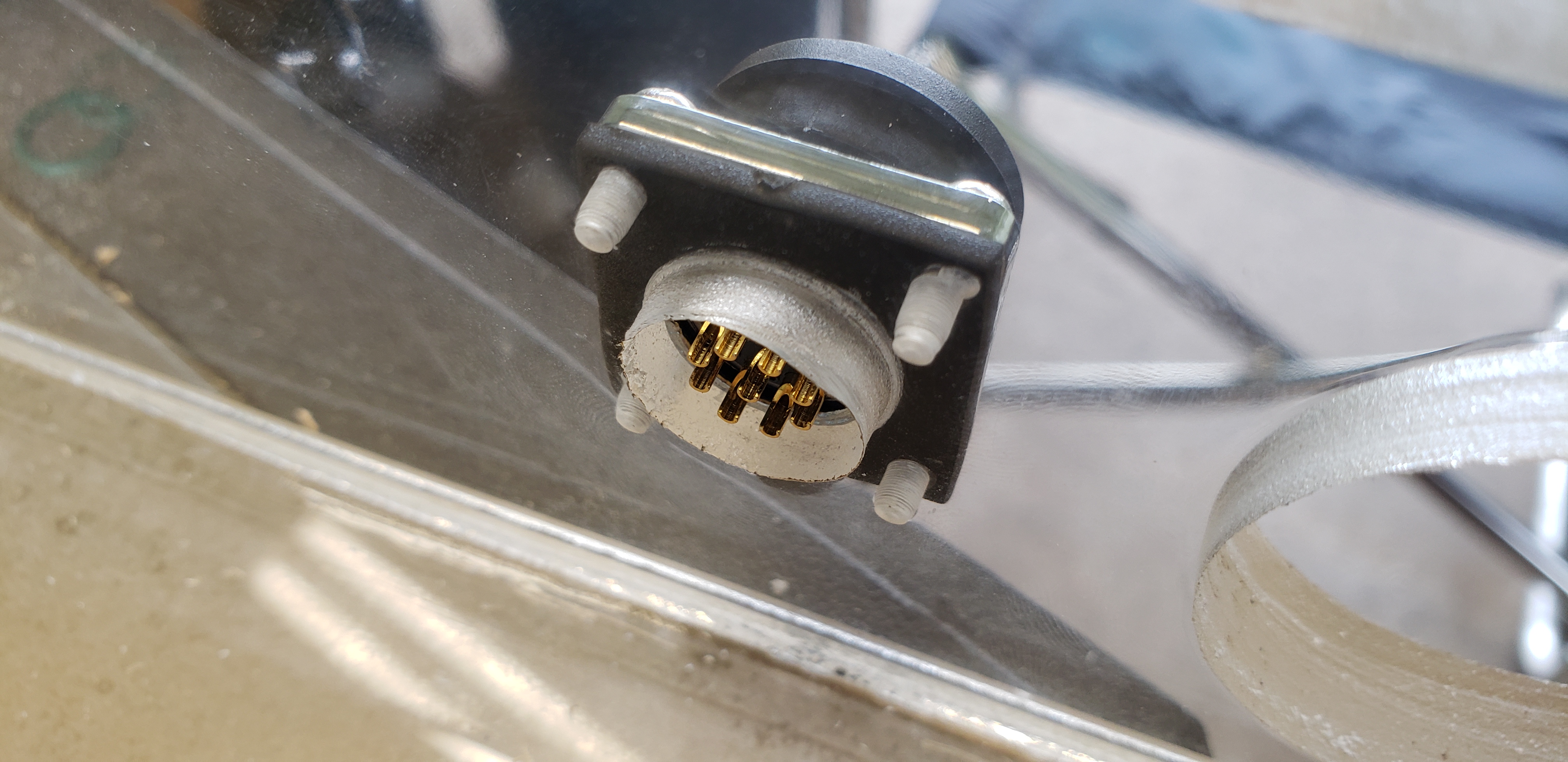
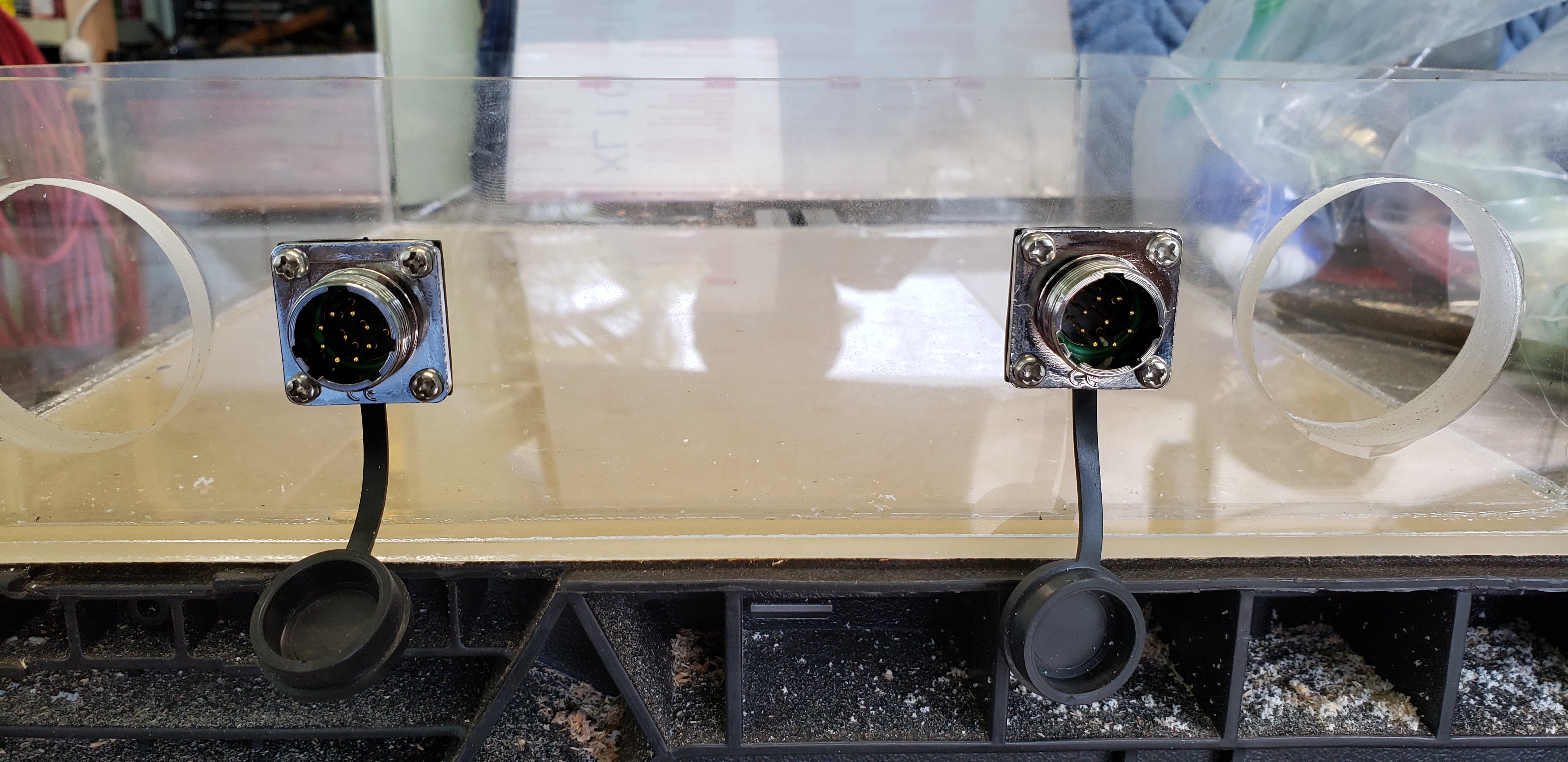
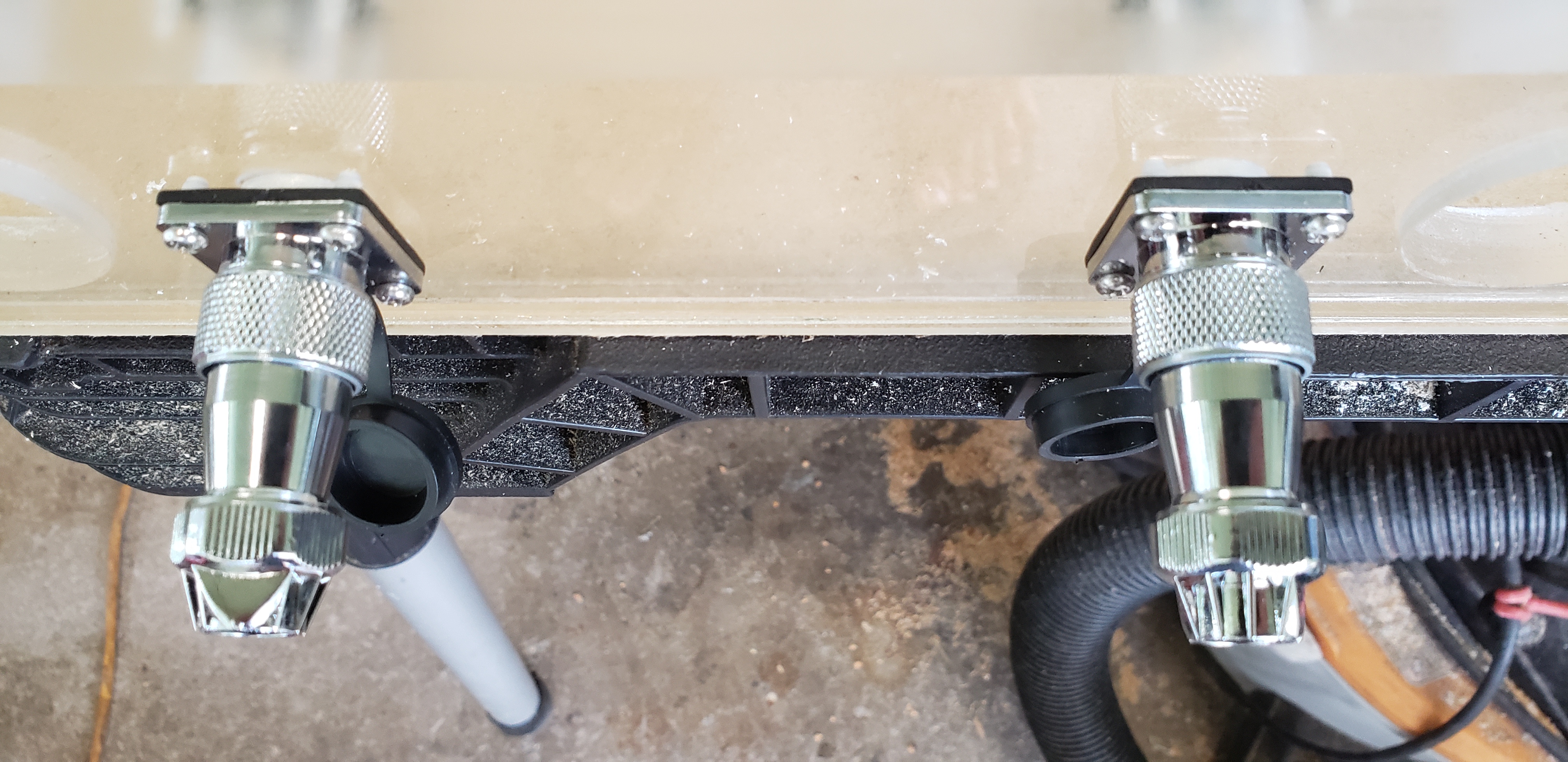
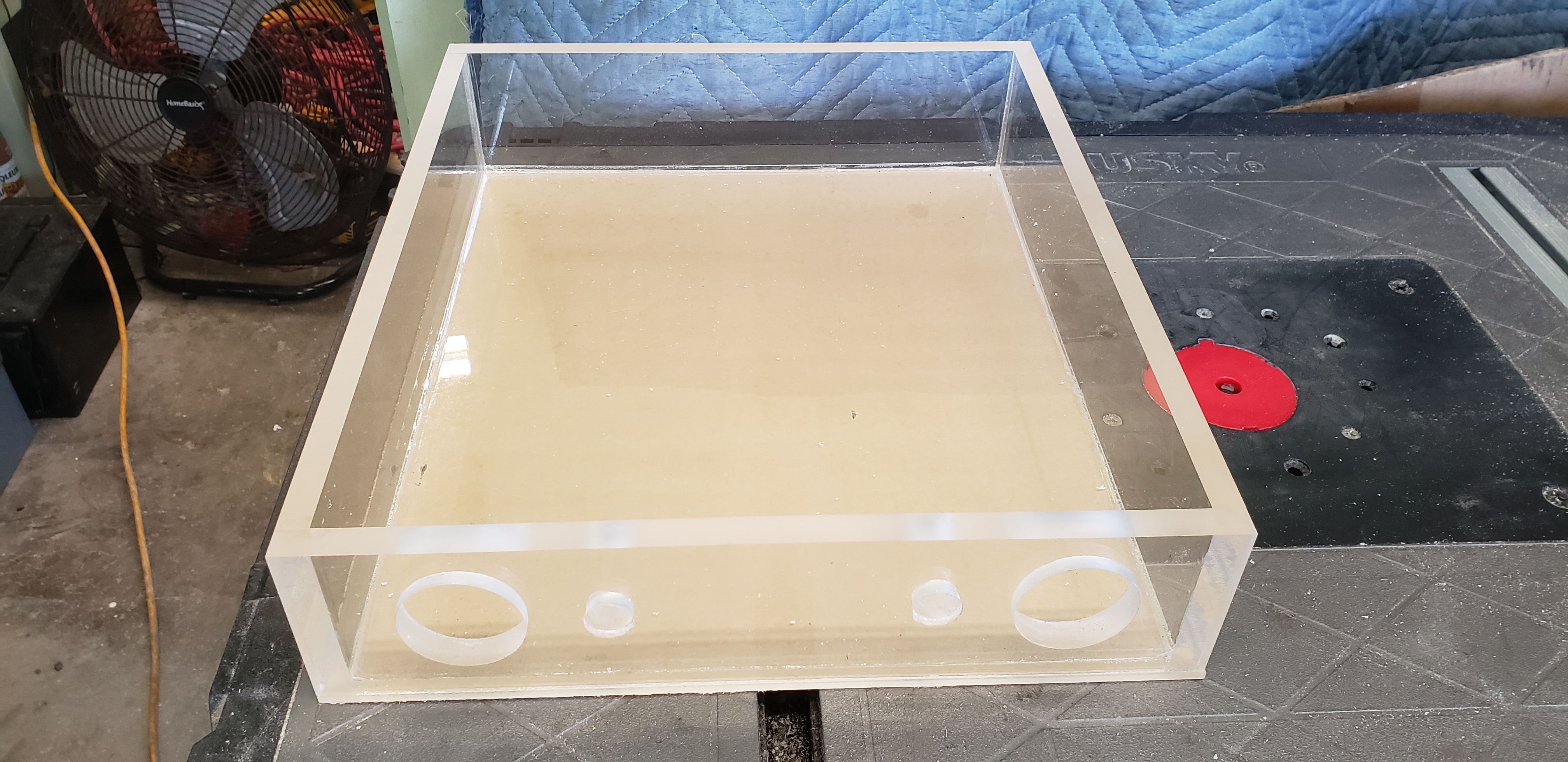
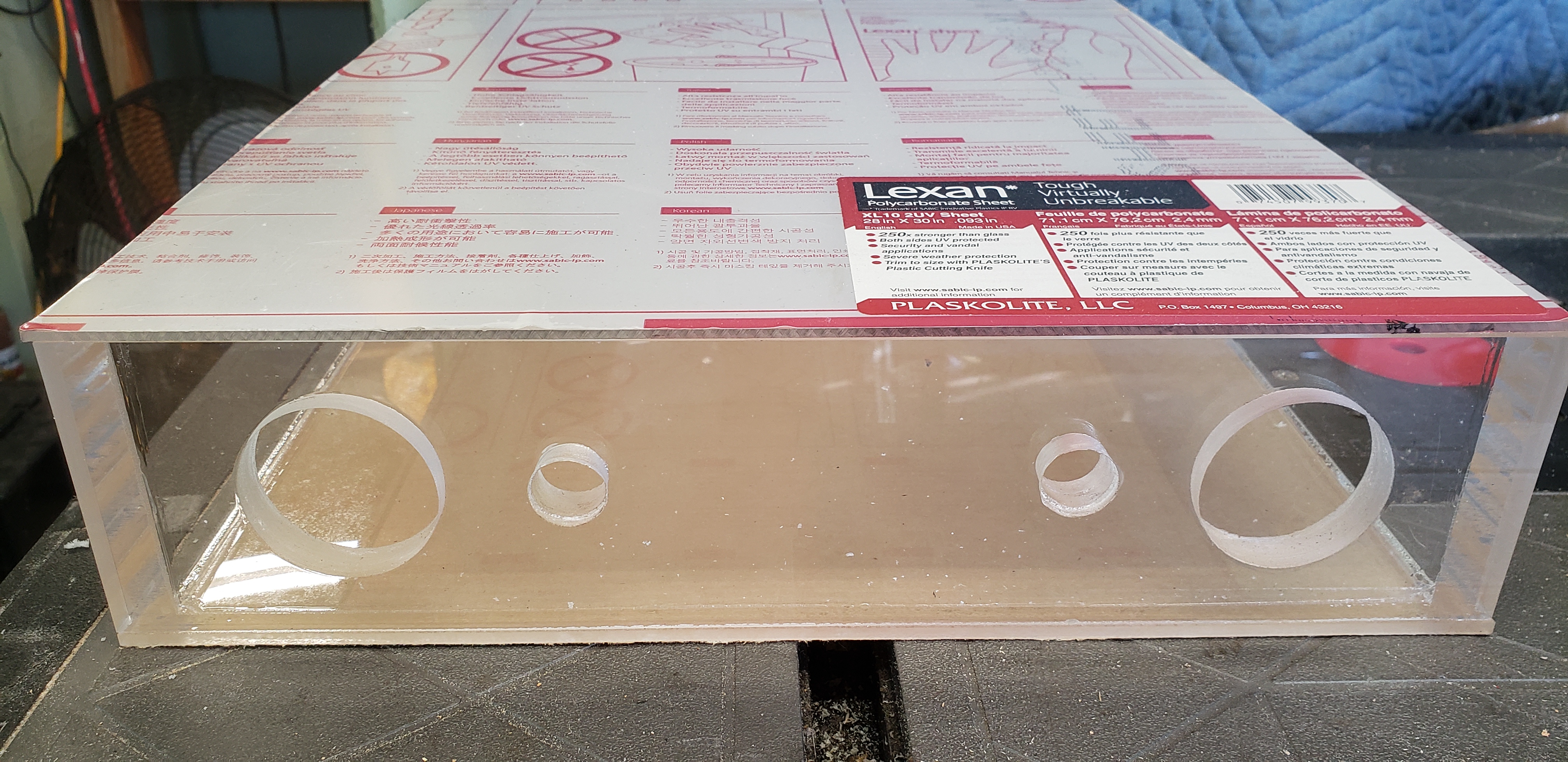
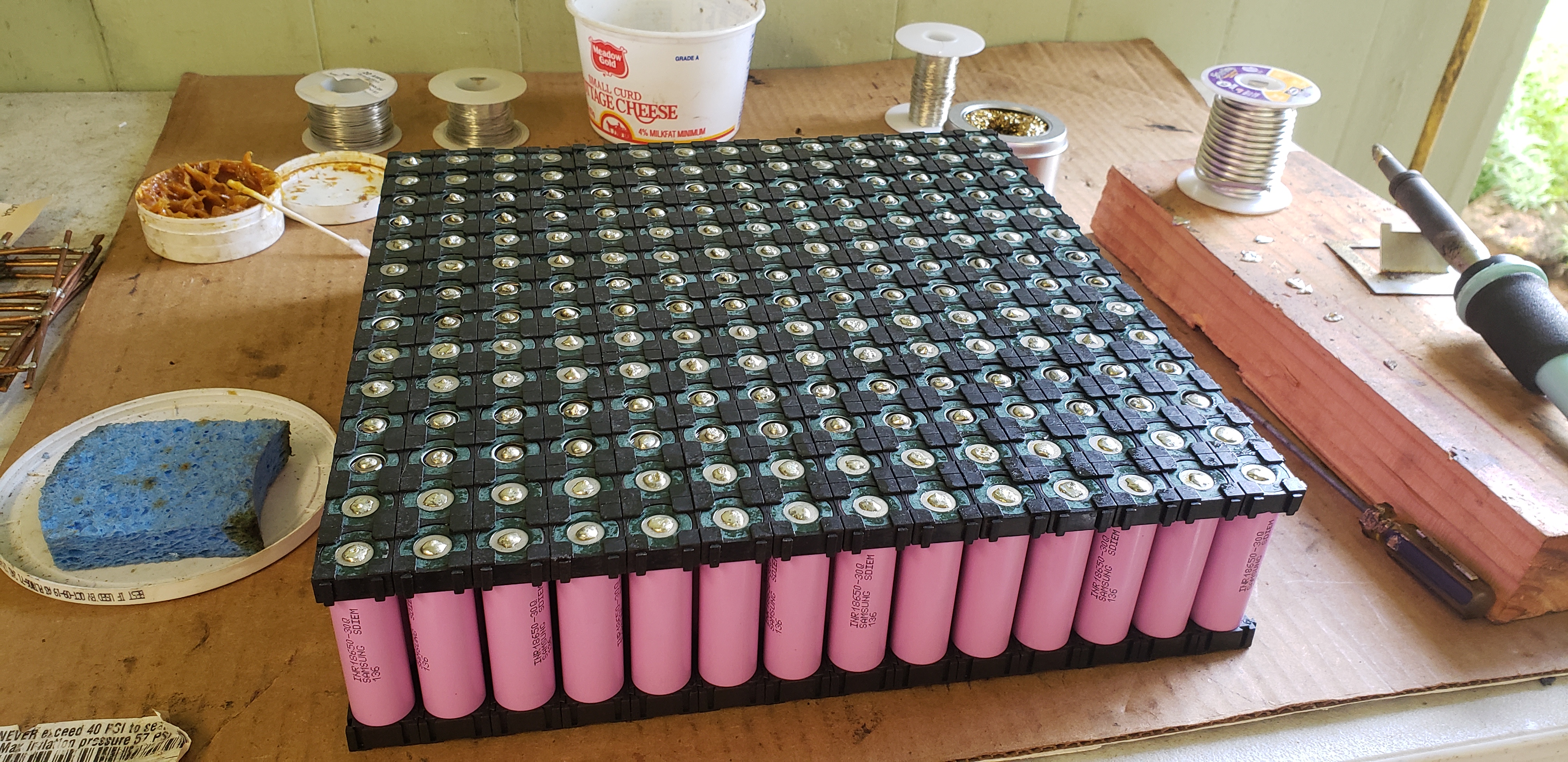
The battery packs are built as two separate batteries. In the waterproof case there are two completely separate 7s14p batteries. They each have their own Marinco battery connector with 200a fuse, and a 8 pin balance lead connector with each wire individually fused in my second build (highly recommend!).

I built it this way because I do not want a BMS
And I balance charge with a icharger X8 that can only charge up to 8s batteries. So, I charge as two separate batteries. But for use they are hooked together in series as one 14s14p battery. Does that make sense?

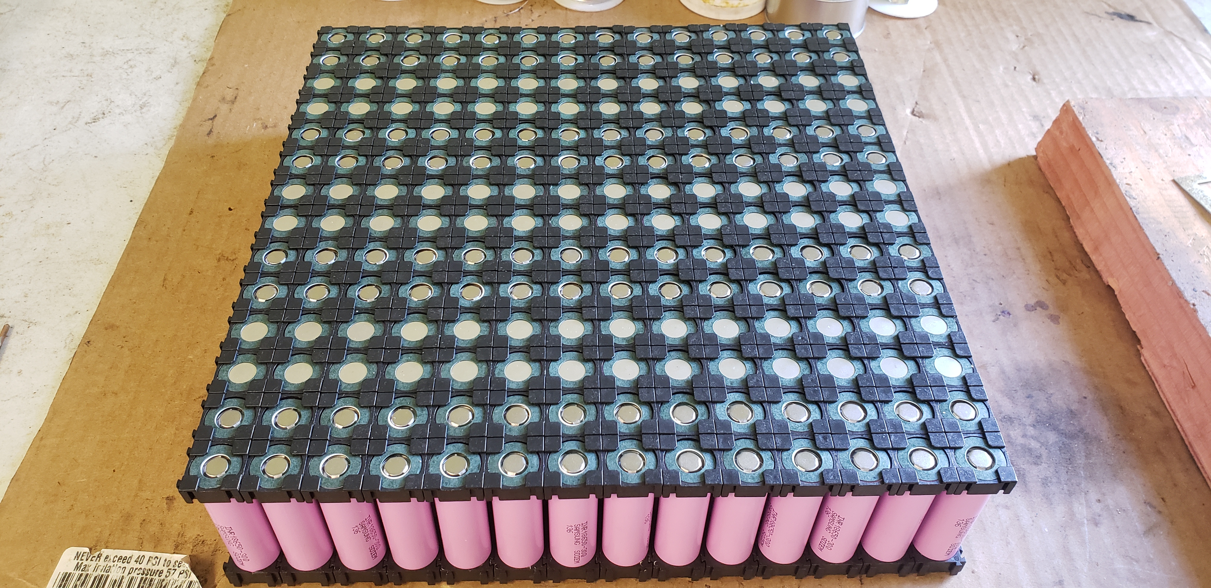
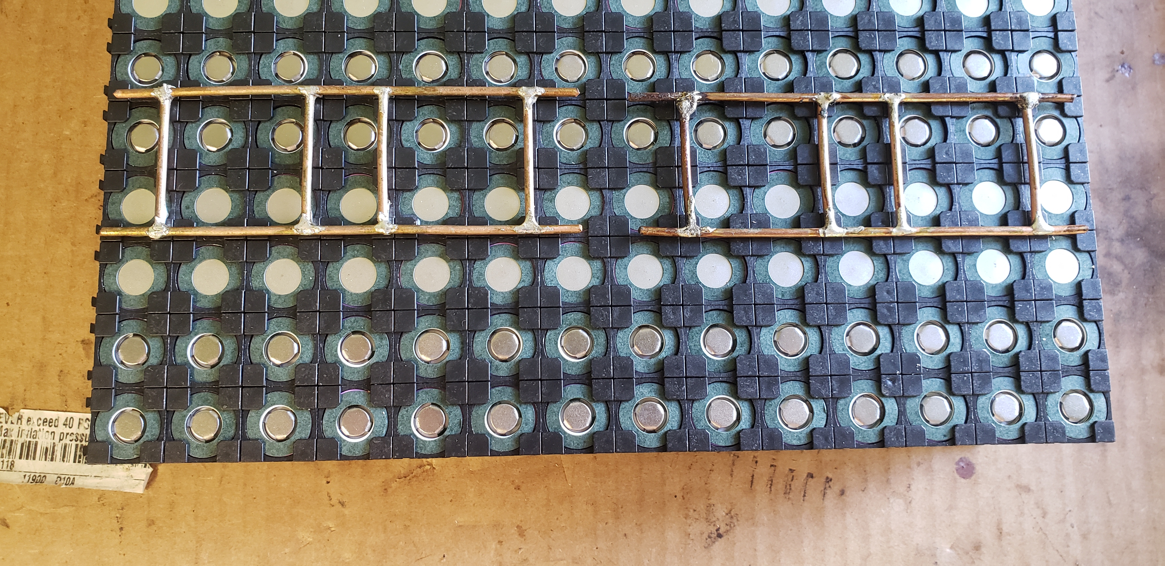
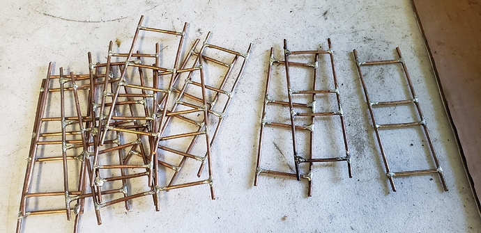
The bus bars that the battery leads hook to are prone to breaking the fuse wires from the pull. So I used a heavier gauge wire (20awg) instead of the 30awg used for the fuse wires. These cells are still fused because the other terminal has the 30awg fuse wire. Hot glue was not a good solution, and is not needed with this modification.

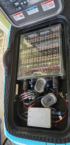
The aluminum box houses the ESC. The two small plastic boxes have the receiver in one and the low voltage alarms in the other. I did not have a long enough external antenna to put the receiver inside the aluminum box with the ESC in my first build in that picture.

I now have a 120cm long external antenna and the receiver has been moved to inside the aluminum box with the ESC. So, now I only have one of the small plastic boxes which houses the low voltage alarms.

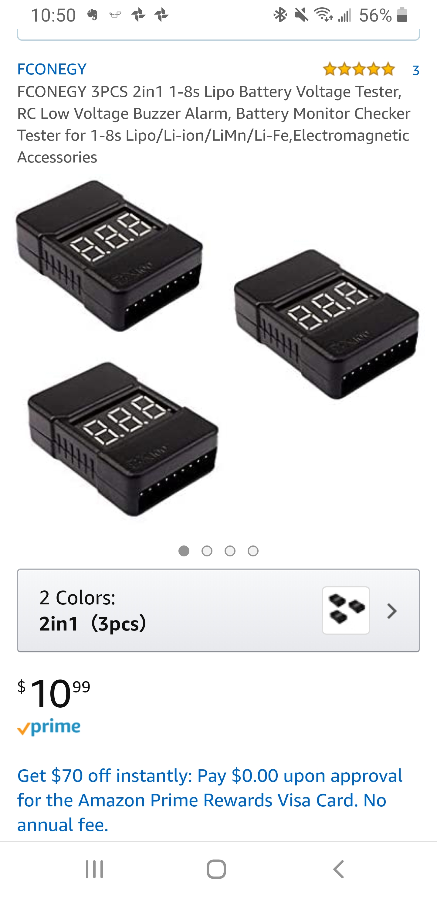
Because there is no BMS it is very important to balance charge the battery, and to make sure never to let any cell voltage to drop below 2.5v during use. The voltage alarms are simply for added security. So I know if any cell voltage drops to the value I set, which is 3.0v. I hear it beeping and have about 5-10 minutes to get back to shore before 2.5v.

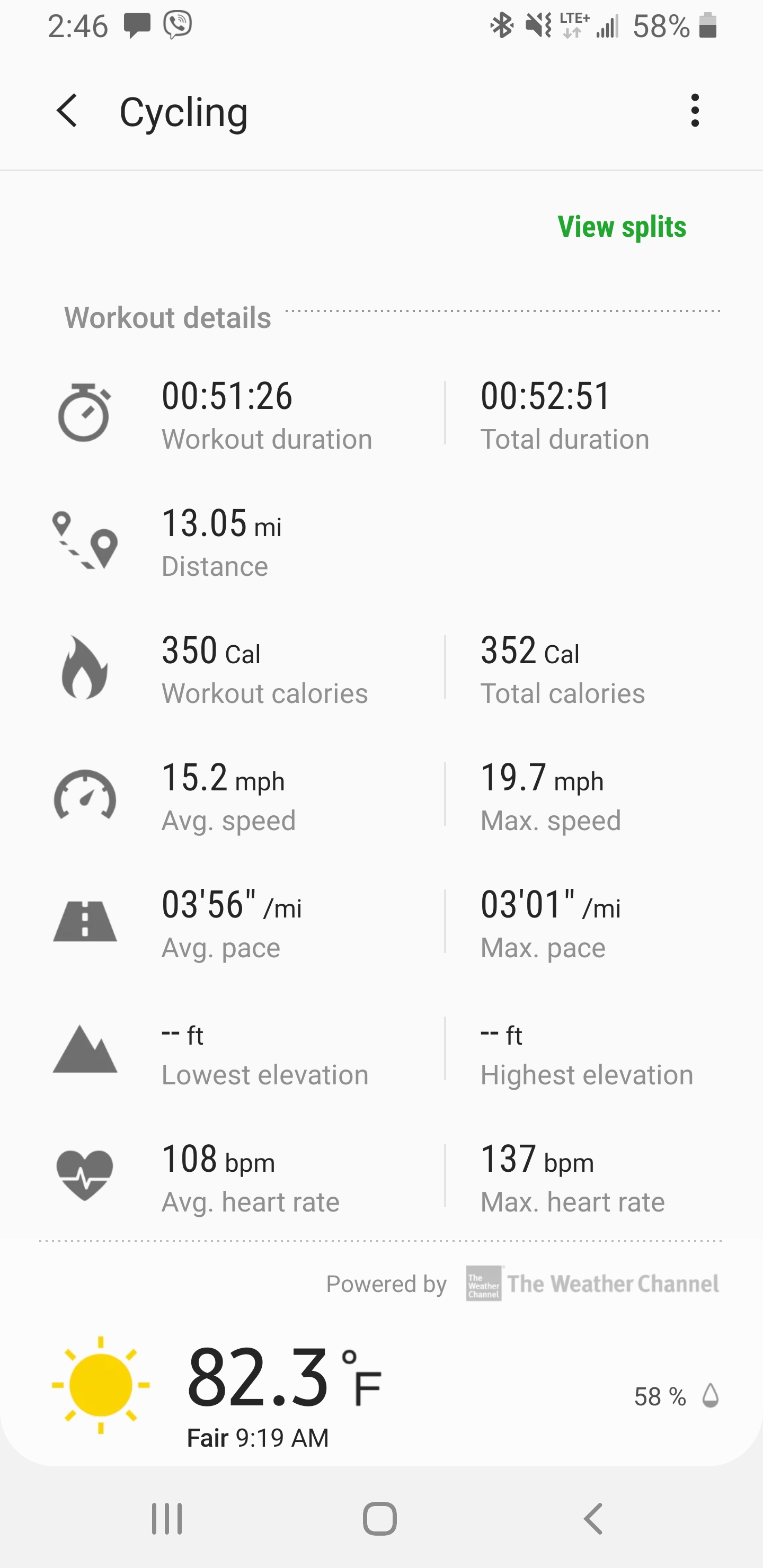
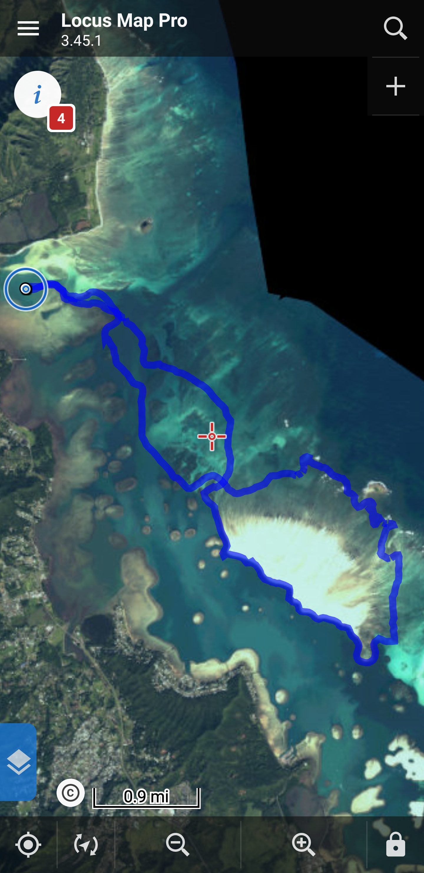
The battery indicator on the remote works well, and I always know when to head back to shore without relying on the voltage alarm. But, I do really long rides by myself, 15-18 miles round trip. If the battery has a malfunction, or a individual cell starts to drop more then the others, the voltage alarm will sound, and I will know to turn around and head back to shore.

I don’t trust BMS. Never trust a BMS!

:call_me_hand:

I was still at 3.5v after this ride. :sunglasses::desert_island::surfing_man::beers:

2 Likes

Yes, I got the configuration completely: 2 x 7s14p, with 2 x external chargers to control charge to each battery, fuses on each battery, fuses for each balance connector, and run in series once it leaves the battery enclosure. All makes sense. I was a little confused on the way you did the series connection outside the enclosure in the trolling connectors, but think I figured it out from the pic.

Busbars -
I called these busbars, but maybe a different name for them -

image

They are held in place by the solder from the fused wires alone? No glue or anything else to secure them?

Small external boxes for the smaller electronics - got it.

On the low voltage alarm, I assume you used something like this low voltage alarm that interfaces with the charger balance connector? So you hook those connectors up each time you put the battery back in the board?

Thanks again - that looks like an awesome 18 mile run!

Yep. That’s the voltage alarms! But, I like the ones that have the plastic housing.

The fuse wire is all that holds the bus bars in place. The 14 wires is more then enough. It’s very secure.

Good luck with the build. Lmk if I can be of further assistance!

:call_me_hand:

1 Like

Awesome, thanks.

If you think of it, could you shoot a pic of the bottom side of the battery? Pretty sure I know what it looks like already, but it would be nice to see the wiring. I only see top-side pictures in the thread.

Thanks!

Here you go. Ignore the desiccant beads all over the place. :sob: The bag holding them failed. Haven’t got around to opening it to clean it out.

:call_me_hand:

1 Like

Thanks again.

What are your thoughts on putting all of the + ends up and the - ends down, connecting the 14 cells to bus bars? Then the negative side could be spot welded (or soldered) with nickel and the positive side would have the extra protruding individual fuses. I understand why you built it the way you did and I think it’s elegant. My concern is bottom side connections. Obviously you’ve made it sturdy enough, where it is not a concern. Still it seems like continuous pounding on those copper wires could become a problem and looks hard to build.

Since I am about to make a Bunch of these, I’m thinking about how to streamline the building process. Any thoughts there would be greatly appreciated.

Hi.

I don’t spot weld. I solder everything. But, yea. There are a million ways to build a battery. This is just the system that I designed and engineered. It works for me. Yes, it is very time consuming. It probably takes me about 36 hours to build this battery from scratch. Including the waterproof case, plugs, and everything.

Post a build of how you end up building your battery. It will be much appreciated by this efoiling community!

:call_me_hand:

1 Like

Hi guys.

I just completed my second battery build. I just need to round the corners and add the handle.

This is a really good setup if anyone wants to build their battery and waterproof case from scratch.

I’m putting together a parts list and adding up the price and hours. I plan to post these details later.

The see through case is really nice for inspection. The tape in the corners that is red on the bottom and white on the top is water detection tape. The top turns red and stays red if it detects moisture. The bag in the back is desiccant beads.

I’m gonna order more cells here soon to build a 3rd battery.

:call_me_hand:

8 Likes

Nice and with mini fuse :+1:

1 Like

Nice build, looks solid!
Noticed that you have different connectors for the bms leads. Was the short you had on the other pack the primary reason?

1 Like

Amazing work :clap:
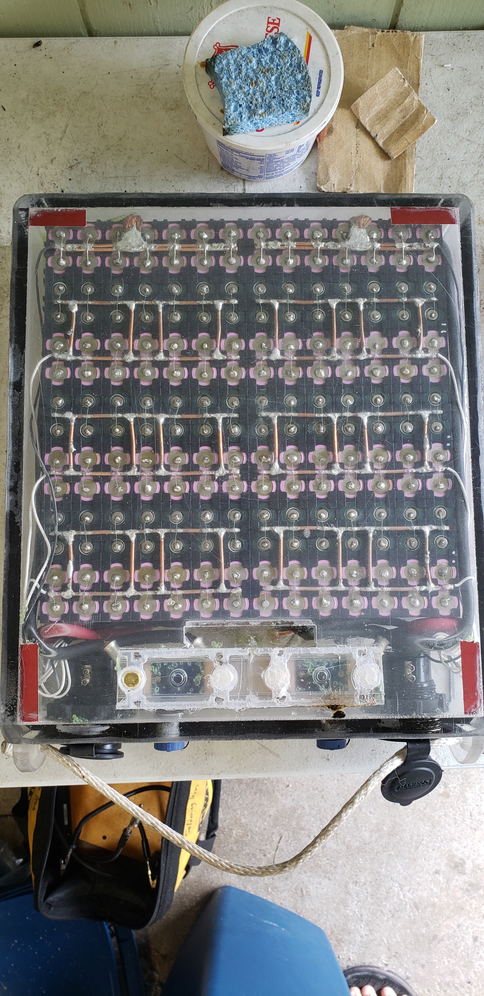
. Thanks for sharing it with us @Flightjunkie.

1 Like

Hi.

The short circuit was caused by corrosion in the plug. The solder connections are so close together that if they aren’t sealed very very well the corrosion will grow across the contacts and cause a short. This is what happened.

The system I use now: After soldering I coat with conformal coating. After dry I do a second coating then before dry I apply heat shrink tubing to each contact. Then I fill the plug with silicone grease making sure no air remains inside.

I had the plastic plugs glued into the acrylic. I am experimenting with metal plugs that have screw fastening. I will let you guys know how I like these plugs after some use and time in the salt water.

:call_me_hand:

2 Likes