So I was able to test the remote reception this evening and the receiver is working ok inside the aluminium box, I assume the signal his passing through the plastic glands and rubber seal. I was even able to move to another room with a cavity wall still working no problem so fingers crossed it works the same on the water
1 Like
Great work but Just a word of advice for the future, epoxy will not bond properly to the pain on the board and you need to make sure you take the paint right back so you ar bonding directly to the fiberglass to get any real strength.
Ok, some more progress!
I spent an hours sanding the board with some liquid encouragement 

And started painting with a epoxy paint, bottom and top side
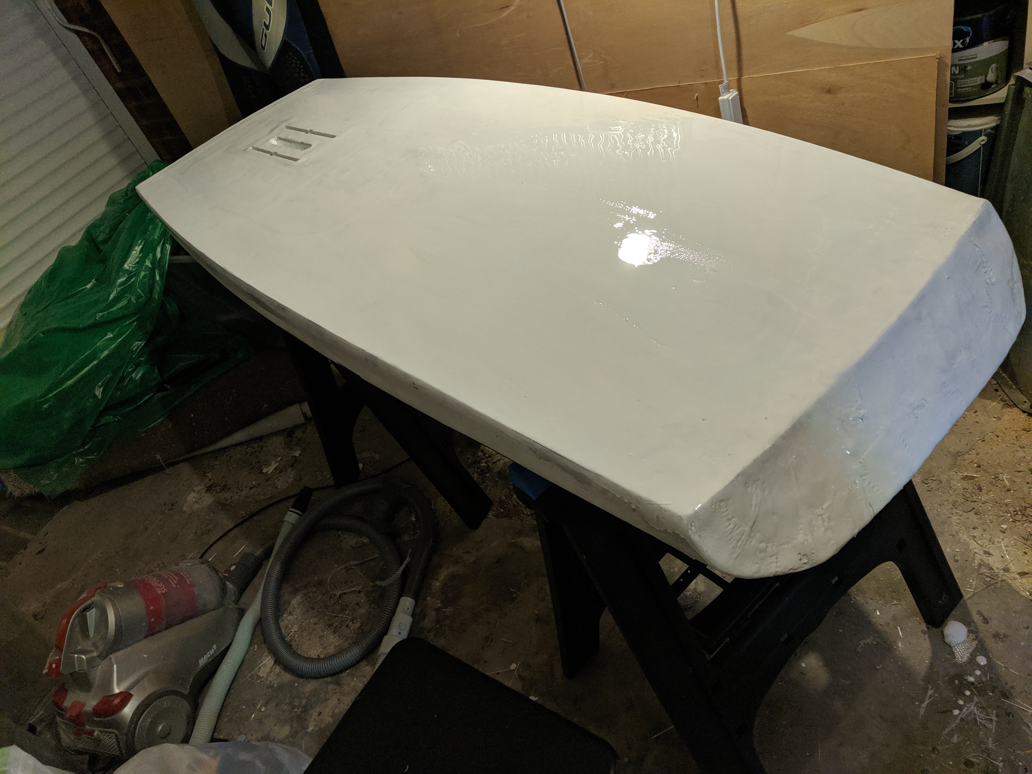
Between coats a full wet sanding,
I have the second coat to put on the bottom, and then another wet sanding planned. I did think I might try to finish the board with the epoxy white, but drips are being too much of an issue, so I’ve got some epoxy white spray paint coming to do the final coat. before the hatch gets fitted.
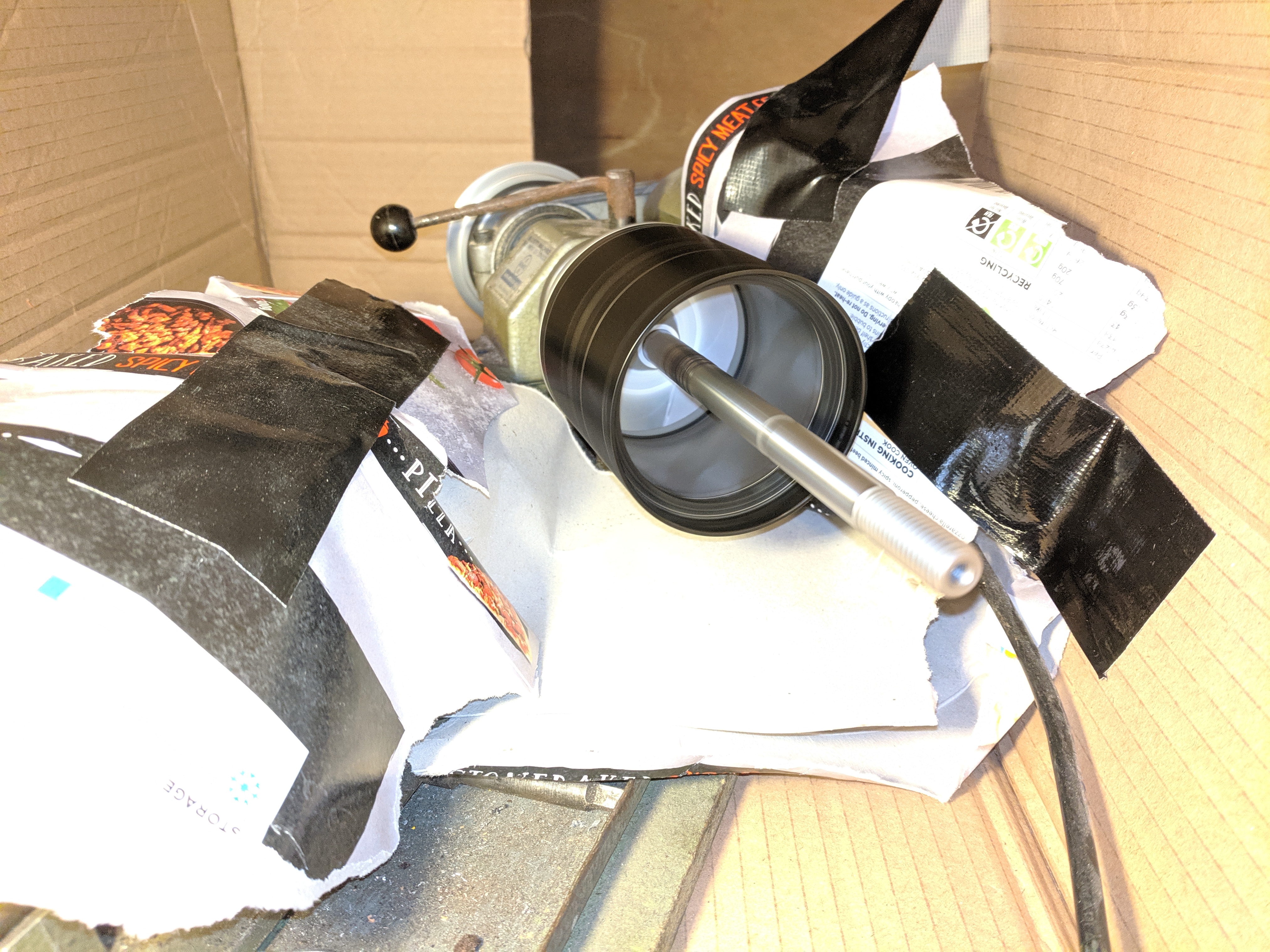
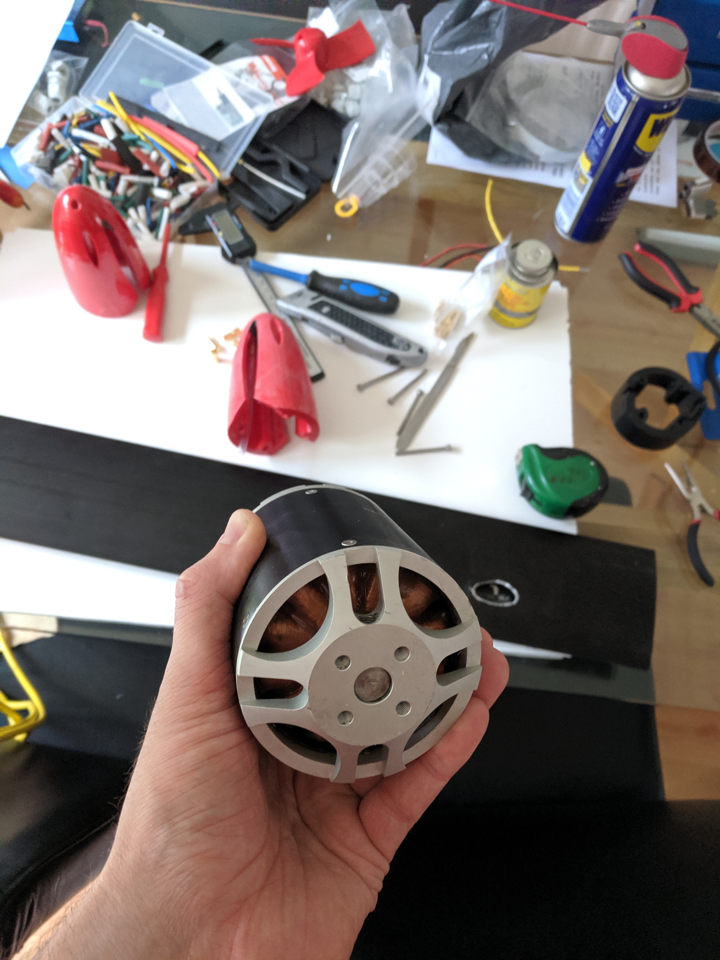
Work also started on the motor.
FYI, I’m not using the original shaft so used this whilst gluing
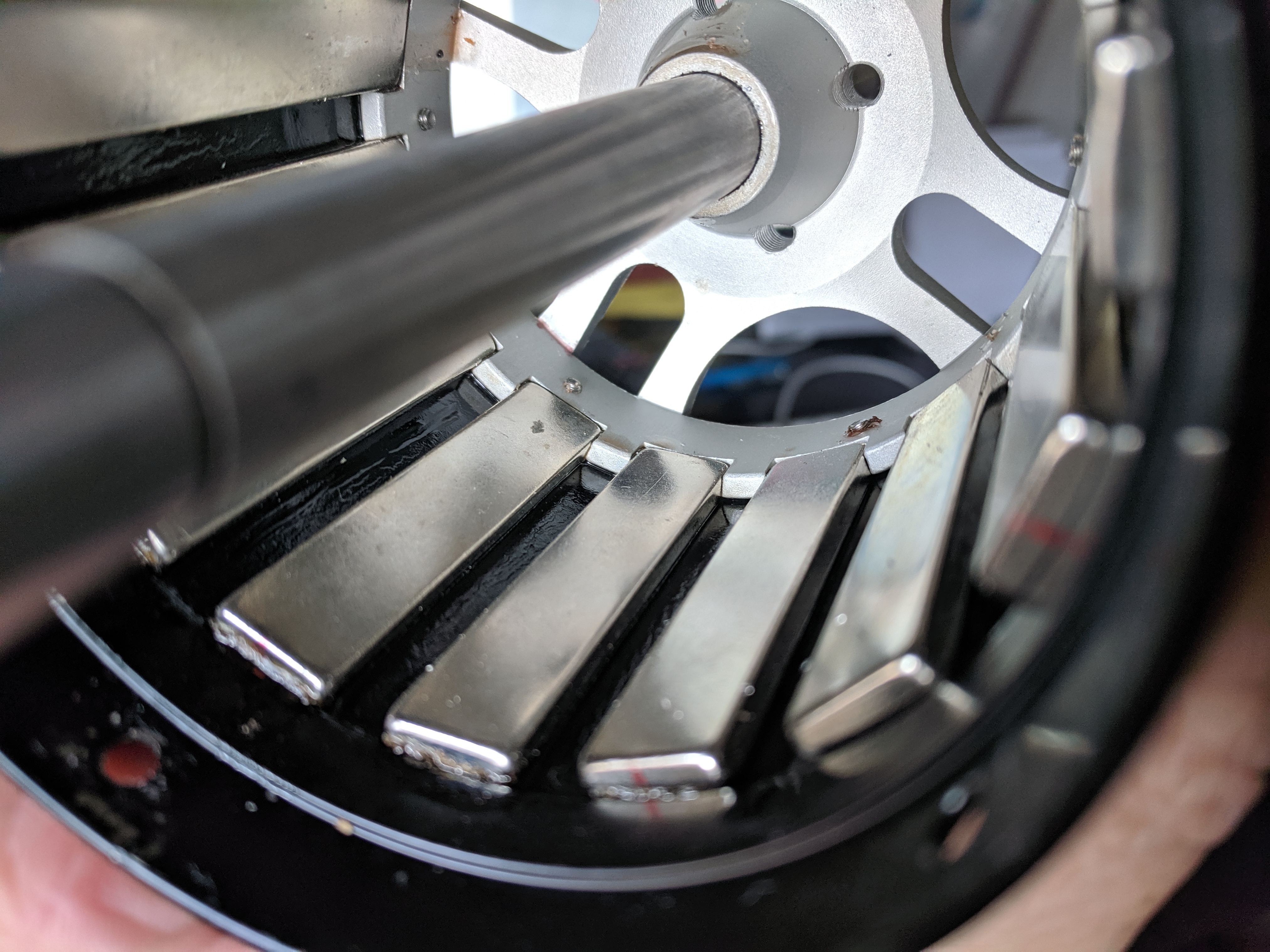
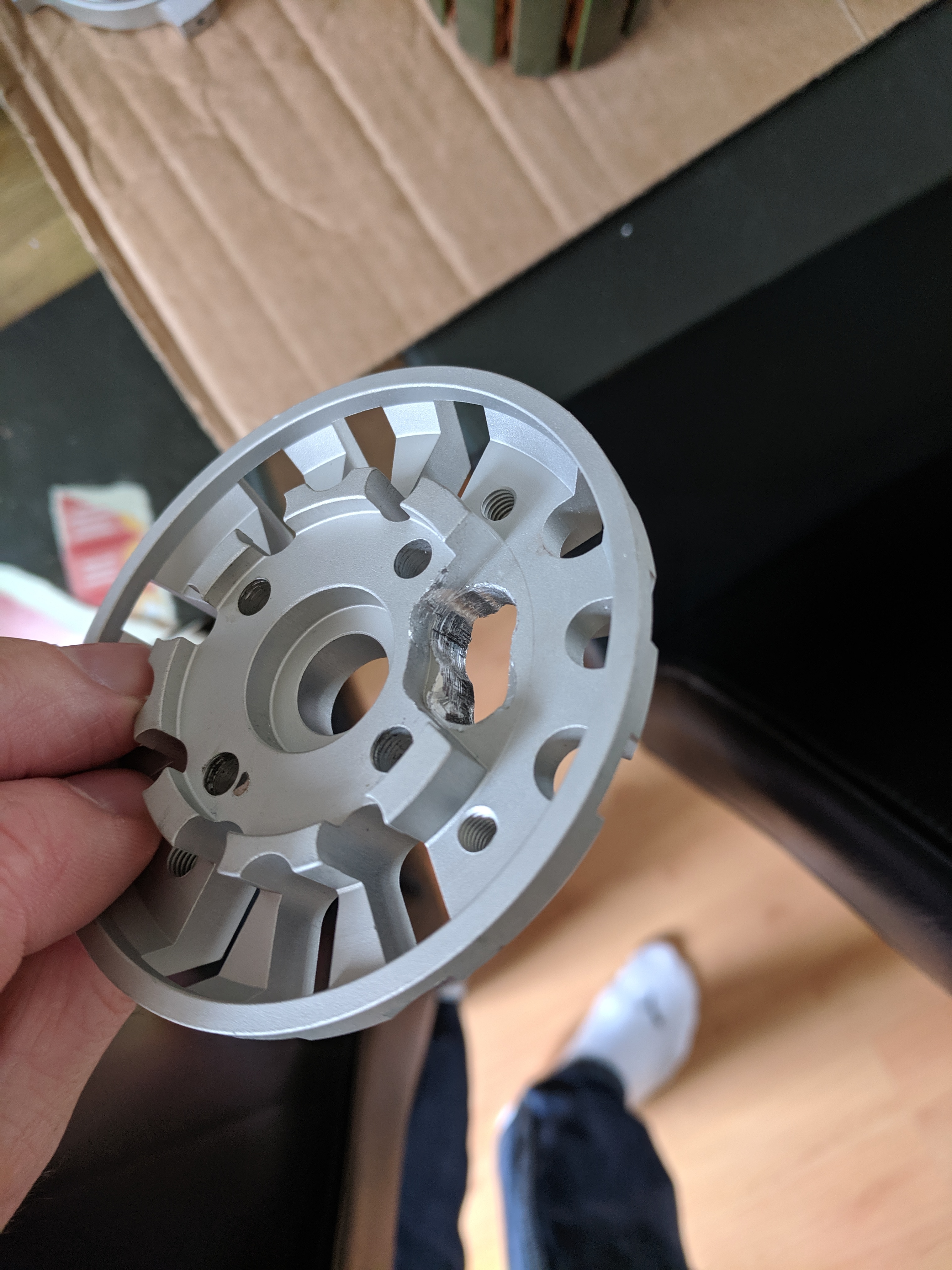
The bell housing first, using the centrifugal method.
I ran off some 3d printed rings to go in front and behind the magnets. I measured then tweaked the scale to get a good fit.
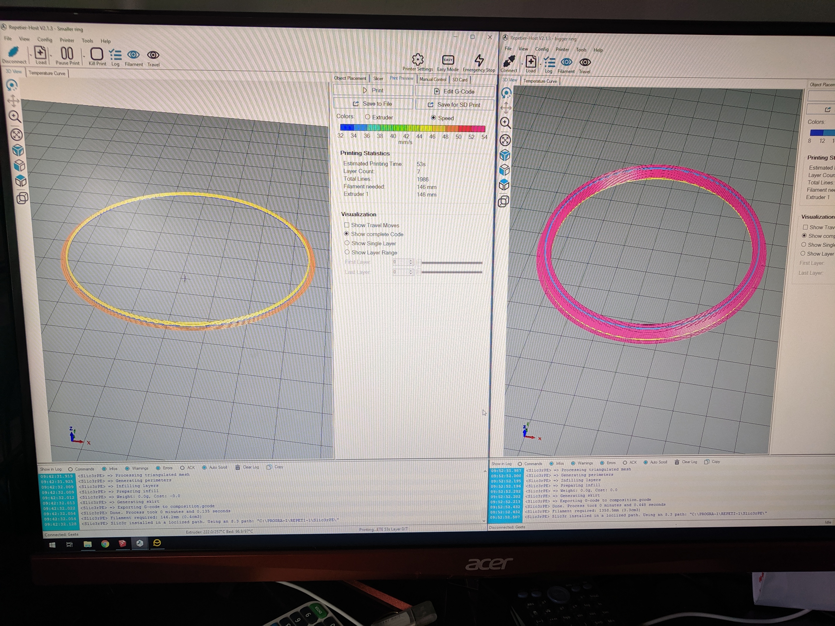
No rings
With front Rings
With rear ring. I should have made the inner diameter a little less on this one as its going to need some finishing.

With the rings glued in, I set up an old Unimat lathe with some ‘Splash guards’…
Also did a test pour with a solvent cleaner to check for leaks and clean where the resin was going.

I went with a polyester resin for this because I could increase the cure time. I know epoxy would give better hold on metal, but with the shape of the housing and the magnets, I can’t see this coming out to easily
The lathe is pretty old and I wasn’t keen on running it for hours straight. Turns out this was a good call as it overheated and tripped out the electrics after just under an hour!
However the pour went ok, unfortunately the pot gelled on me before completely finishing so I had some slightly exposed magnets.
After fully cured, and the lathe cooled down, I gave it a good sanding then had another run. This time I got the perfect finish 

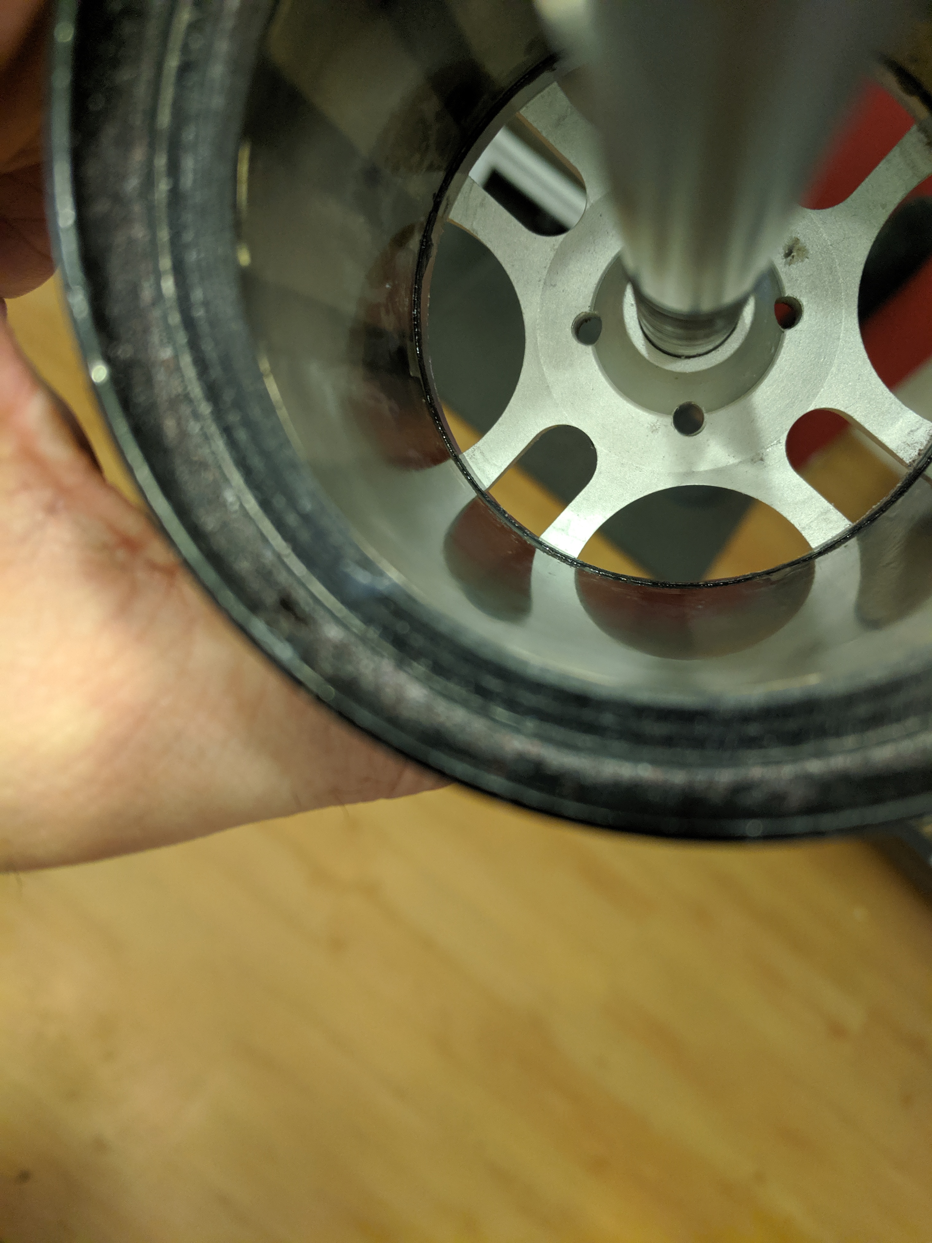
Just a little finishing to do removing the extra plastic from the larger ring and good to go. Pretty chuffed with the results, and the 3D print rings worked like a charm
The windings will be next, I’ve started a bit but waiting on some bullet connectors to solder on before going any further.
5 Likes
Following on from this I used a product from Sicomin - pretty amazing stuff
You can see it being tested here: https://youtu.be/2RFzH_NB148?t=329
Using the slow version almost no heat is produced and its a very slow, calm process letting it fill all cracks.
The only downside is it needs a post cure at 40°C for at least 6 hours. A bit of a bugger considering the size of the board!
I found a solution though, Using a few layers of water proof membrane to protect the board…
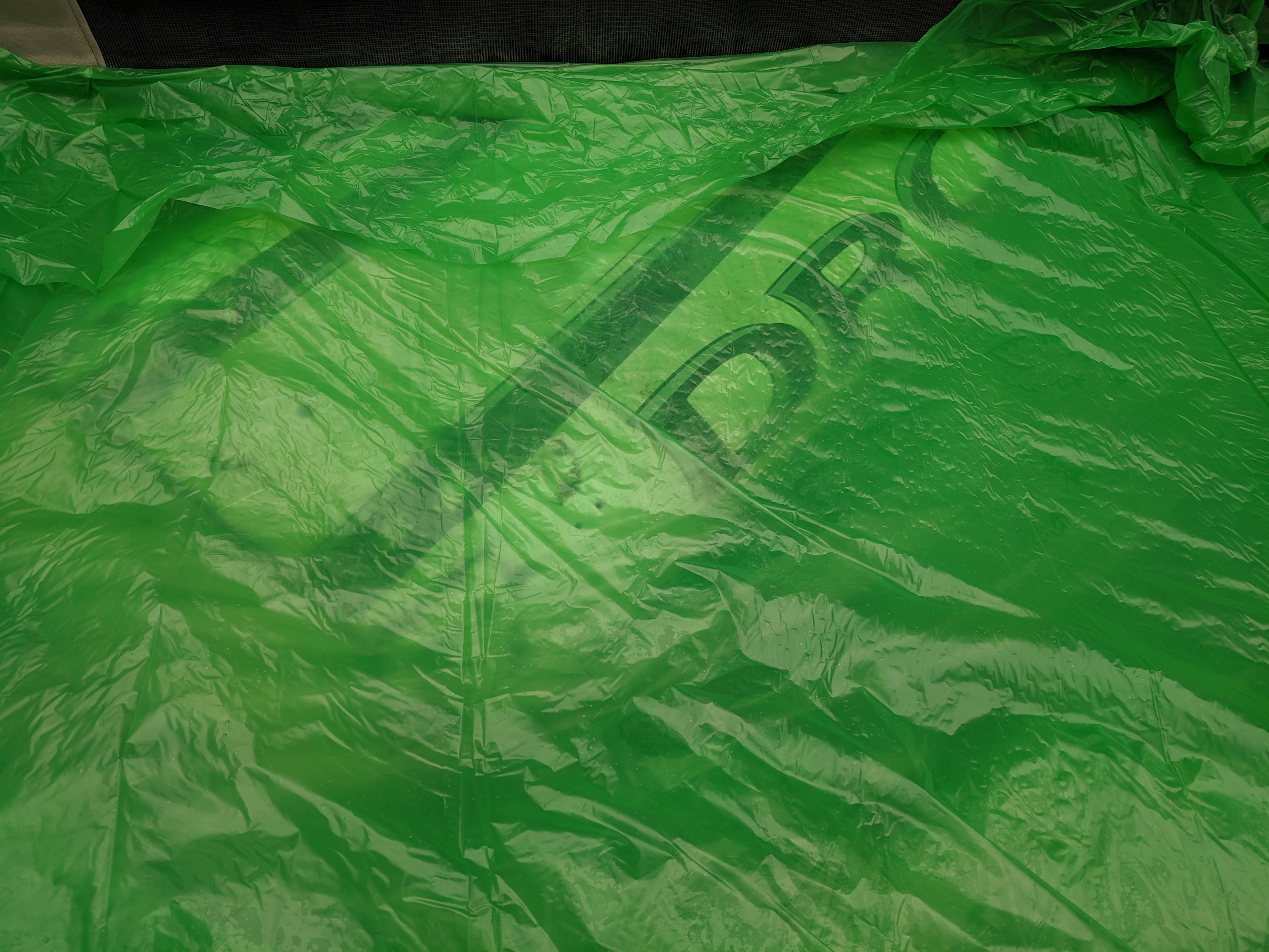
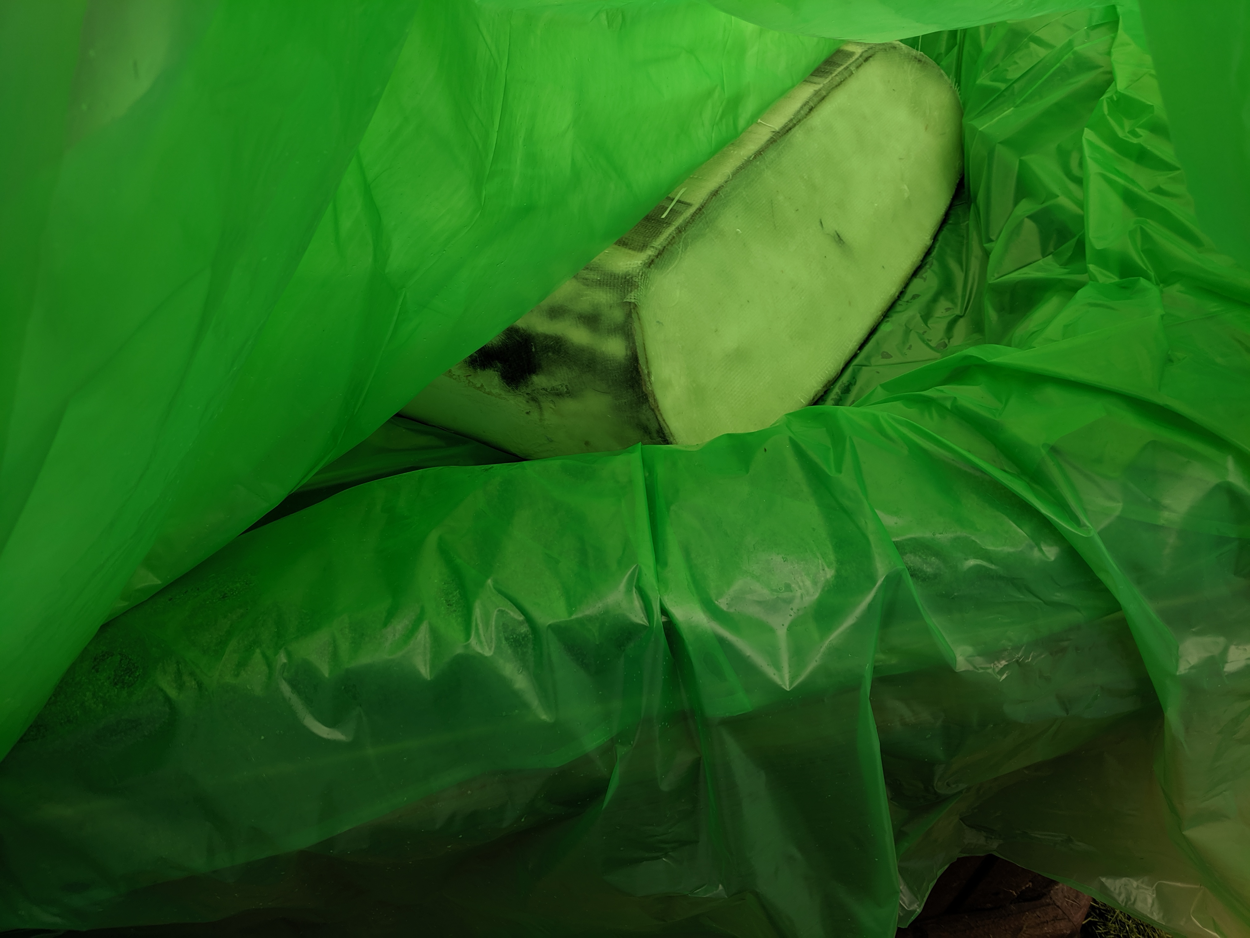
I cranked the heat on the hot tub to 40°C and left it overnight! ![]()
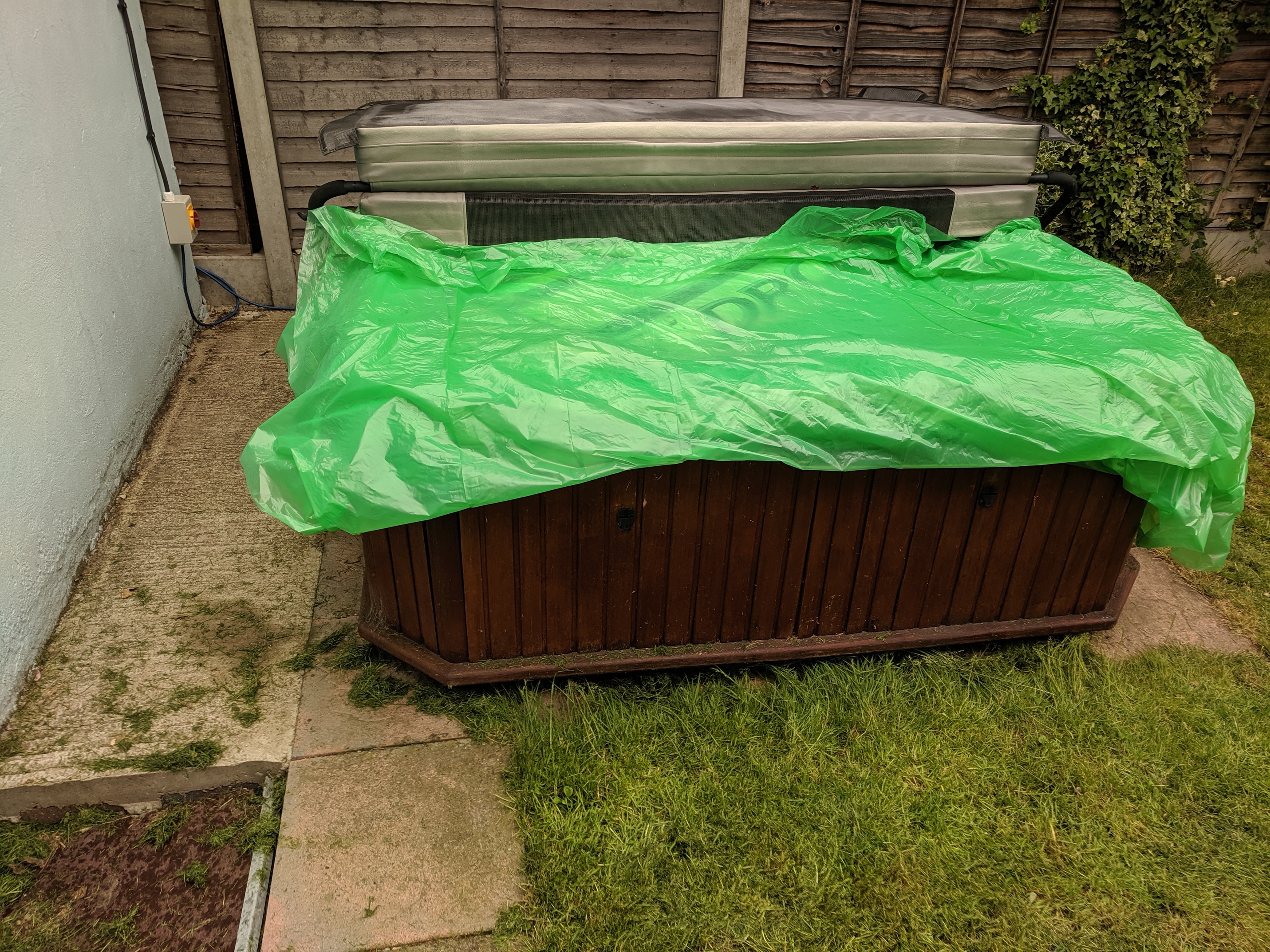
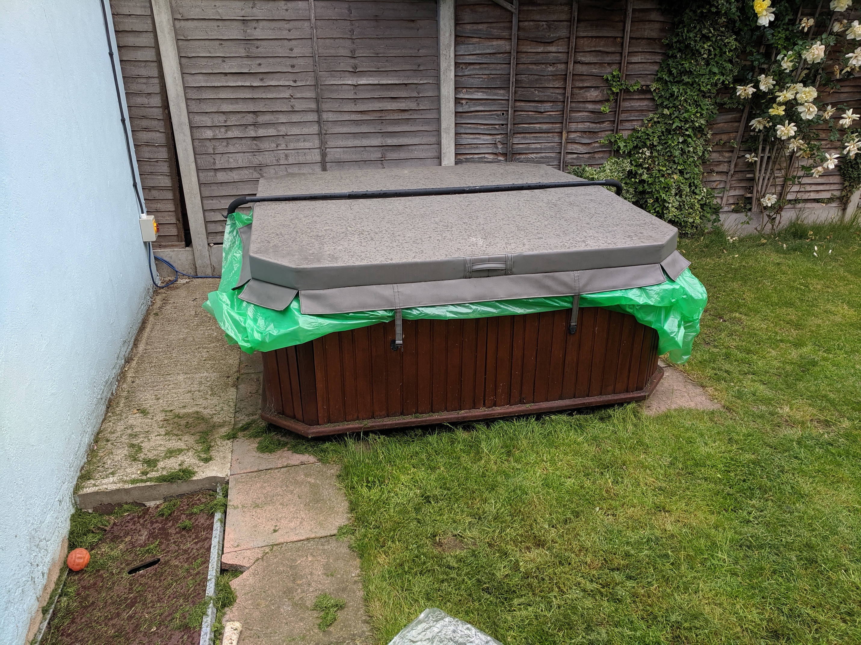
This worked amazingly well! The foam epoxy is rock solid now.
1 Like
@PowerGlider, is that the type of internal mirror surface requirement you had in mind when creating this thread (point 8) ?
Next up is the motor windings. This mostly followed @Mat method. There is a guide somewhere, I just can’t find it at the moment.
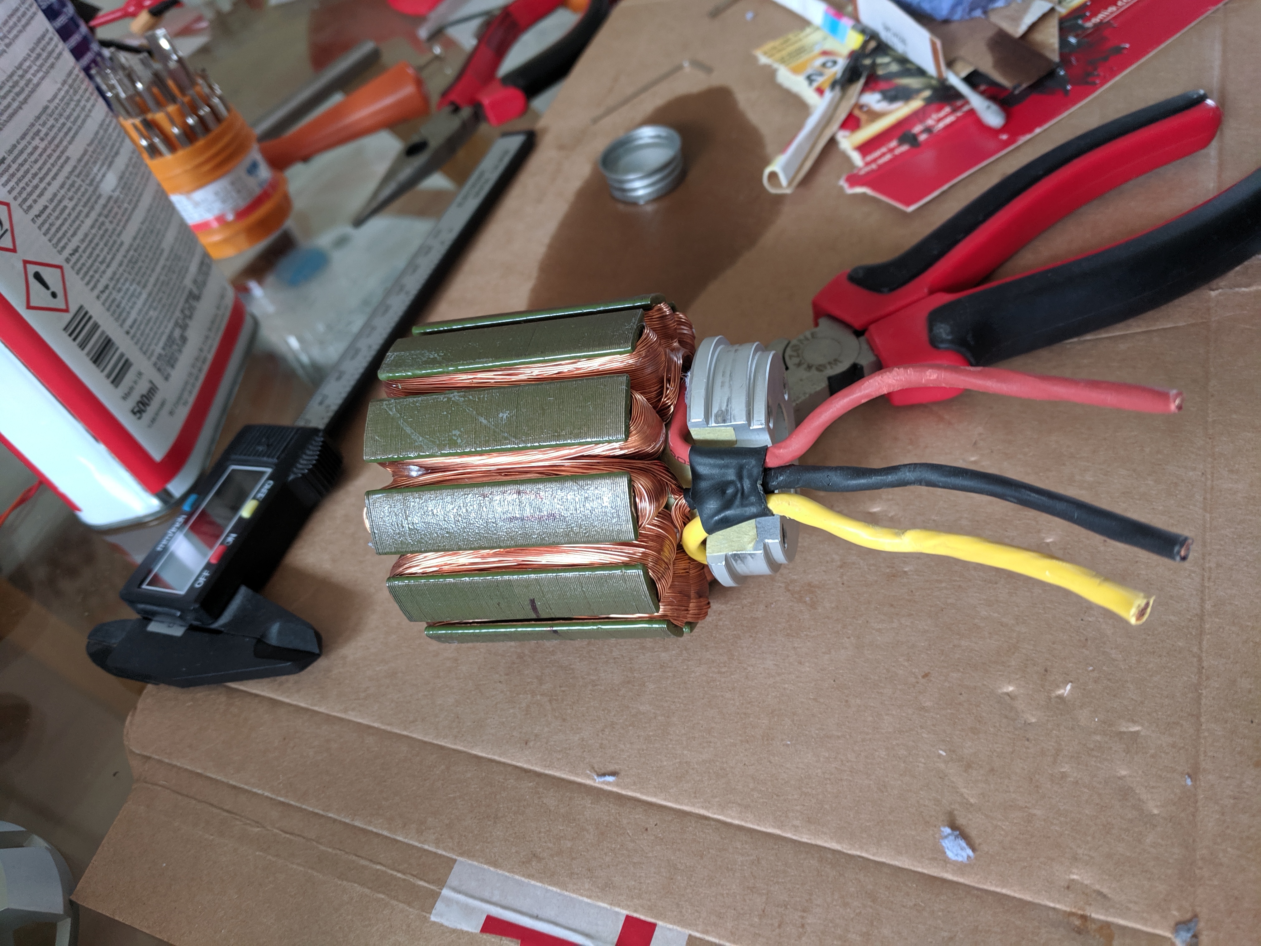
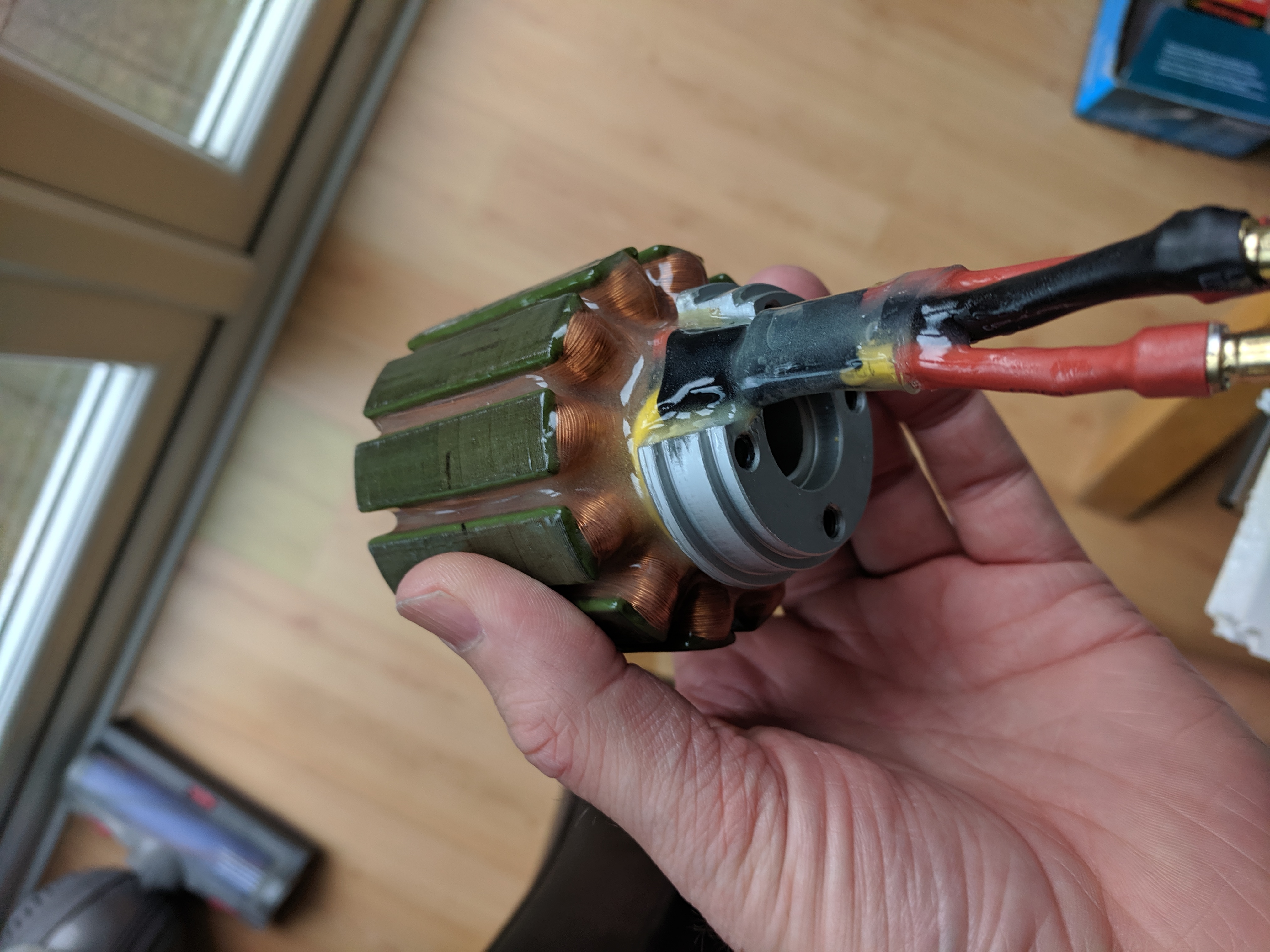
I stripped back the existing heat shrink, coated the wires in epoxy and reapplied new shrink. Note, it would have probably been better to wait for the bullet connectors to be soldered on first! But they hadn’t been delivered and I was impatient!
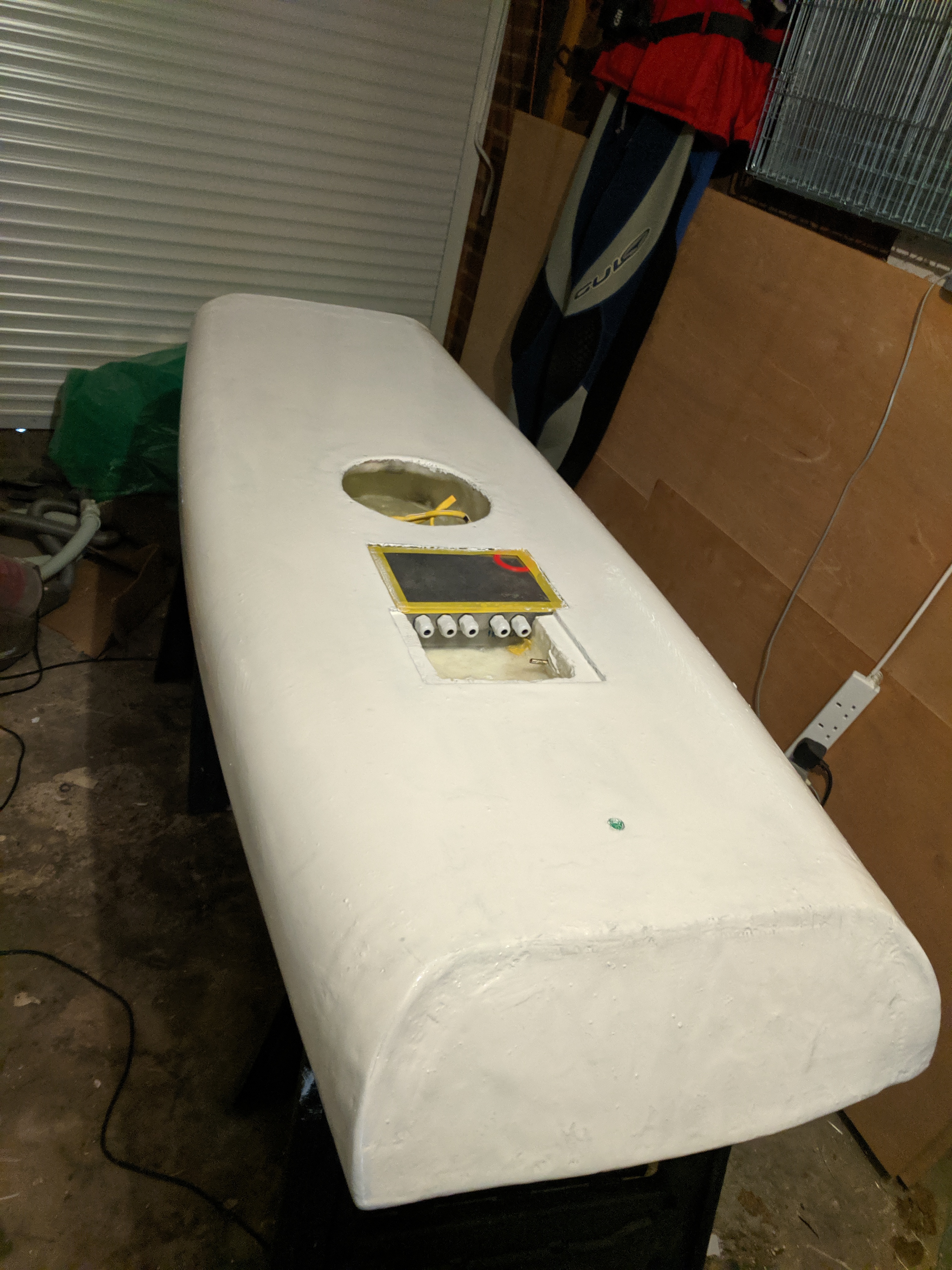
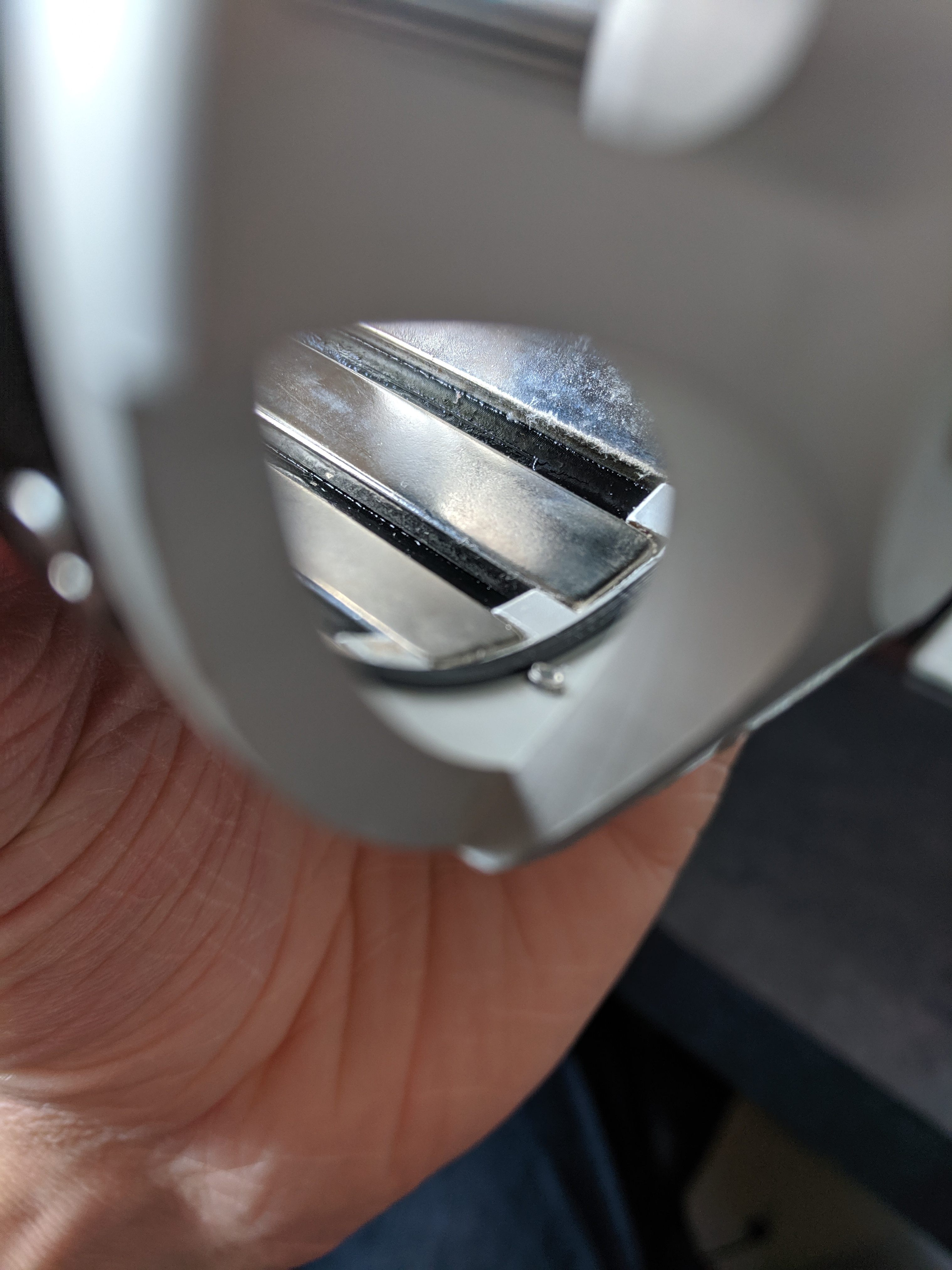
The wires go straight out from the motor now, and I am adding a hole to the motor base, as shown below, for the motors to exit.
The Idea is for the finished article to be a bit like this. So the motor can be easily unplugged without flexing the cables around too much, i.e., the wires are rigid.

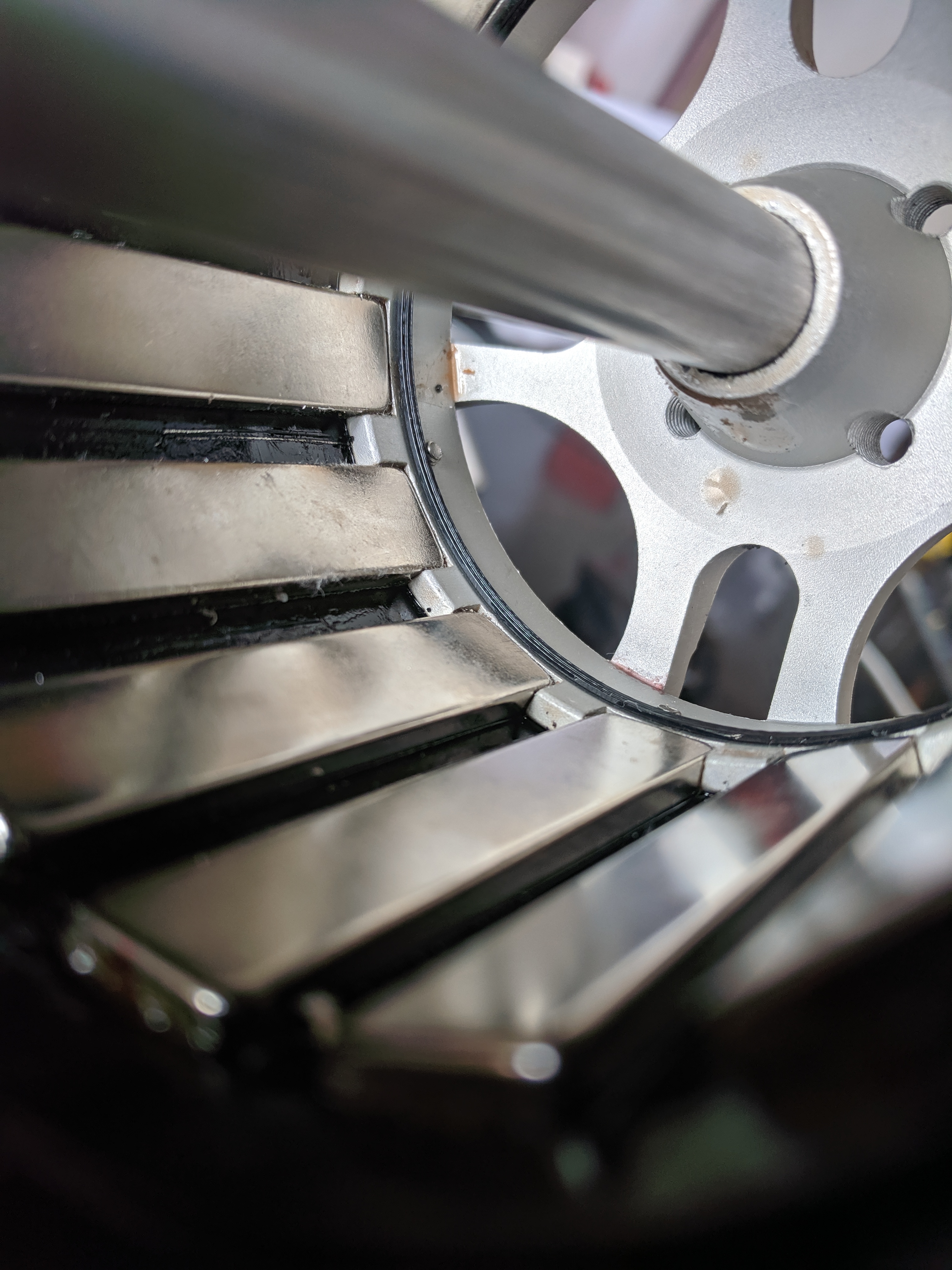
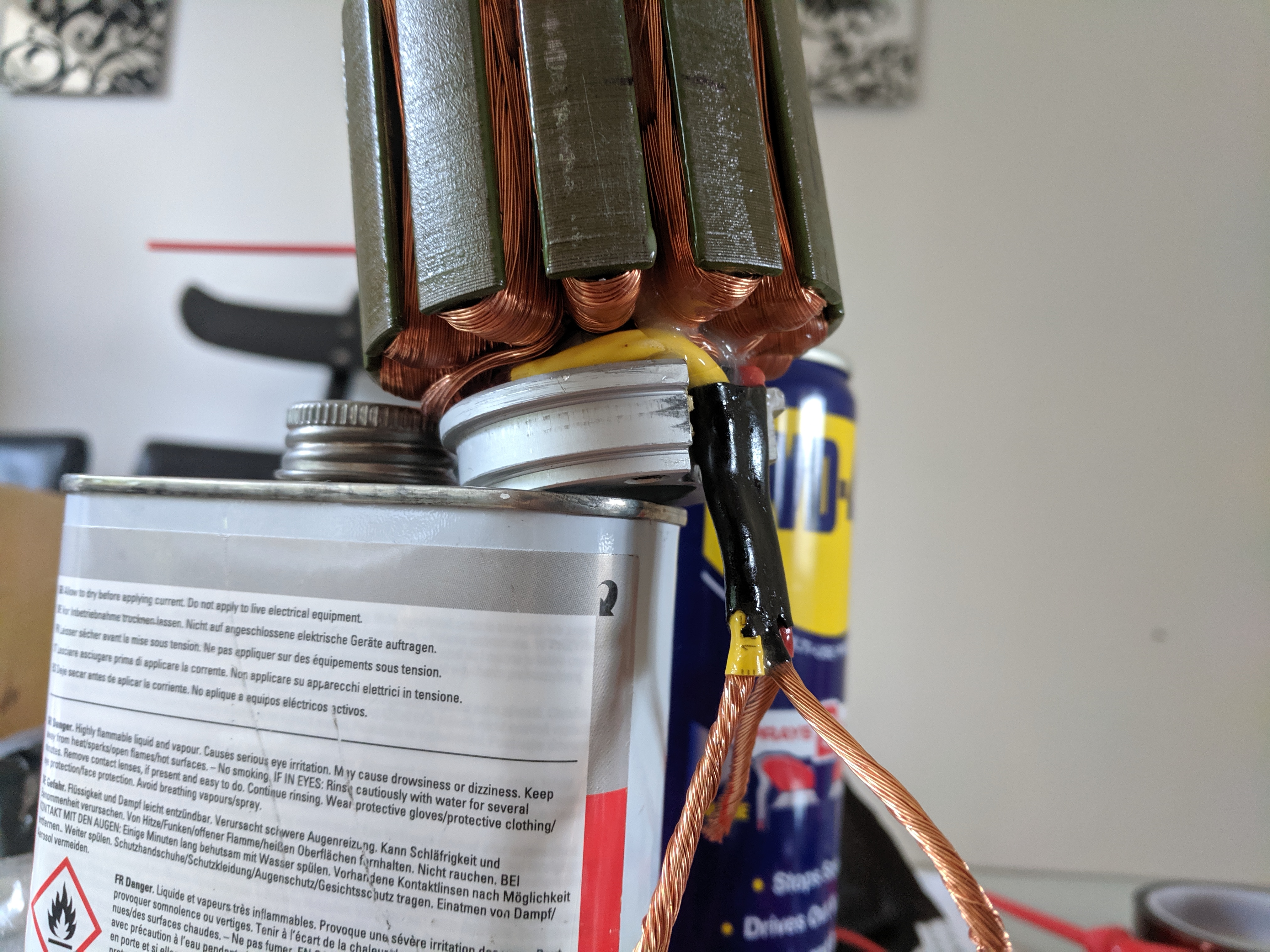
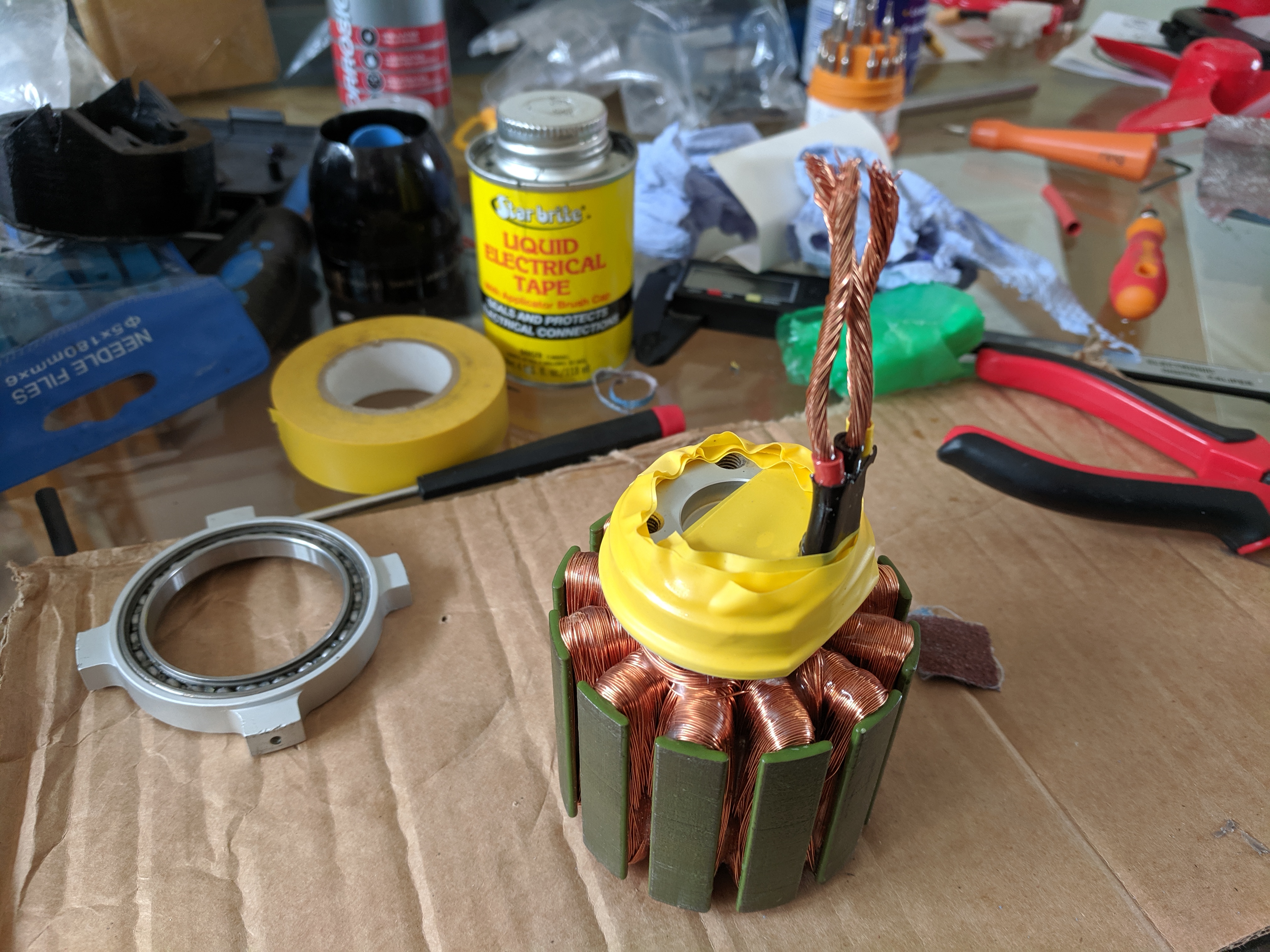
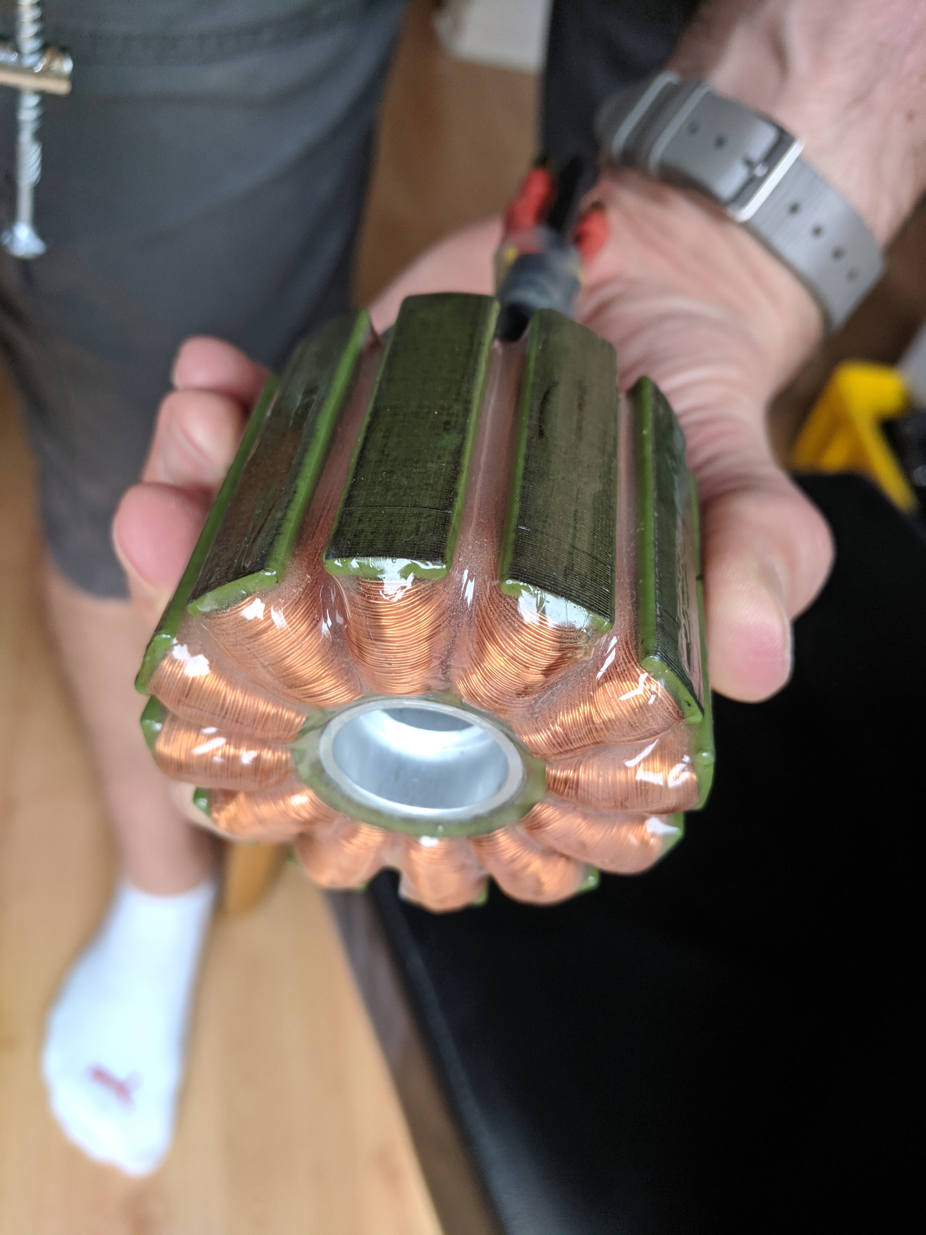
I wrapped a bearing in electrical tape, and taped up any part where epoxy should not go (mainly the bearing holes). I went with Araldite standard slow setting, then spent an entire evening applying.
Basically I covered the whole thing then spent the 90 min gel time keeping on top of any drips by rotating the motor held by one beating on a shaft in a small vice and using a spatula to remove excess every 5-10 mins.
Then the next 3-4 hours, mixing up smaller batches to apply to the tacky epoxy already on the motor (for a good chemical bond) to be sure I got any missed parts.
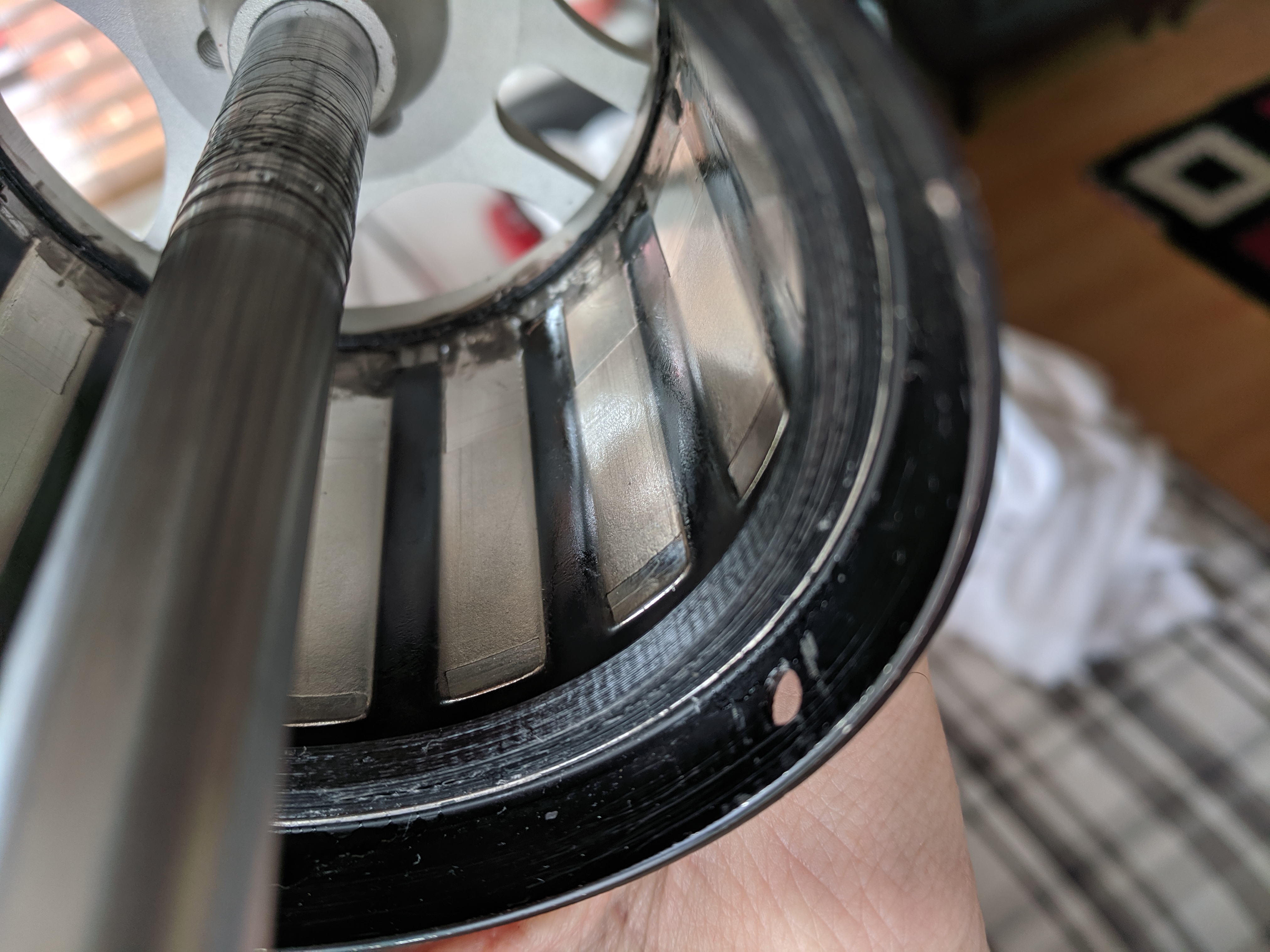
The bullet connectors were soldered on prior to this with no issue (not visible in the pics apparently), and also coated in epoxy right up to the connectors, and then heat shrink applied over them.
The tape was removed from the bearing holes etc. the following morning (6-8 hours), so it had set, but before the epoxy had the full cure and rock hard. I’m pleases with the result so far.

Once assembled, the intention is to connect the phase wires via the bullets, add a few layers of liquid tape (see the parts list in first post) over the joint, and then a covering of heat shrink over the wet liquid tape to seal it all up.
I’m going to look it over with fresh eyes tomorrow and hopefully reassemble the motor this week
3 Likes
Very nice plastic work! I made my coating much much thinner, around 0.1mm i guess. I hope it is conductive enough for the heat. The original thread about epoxying you find here:
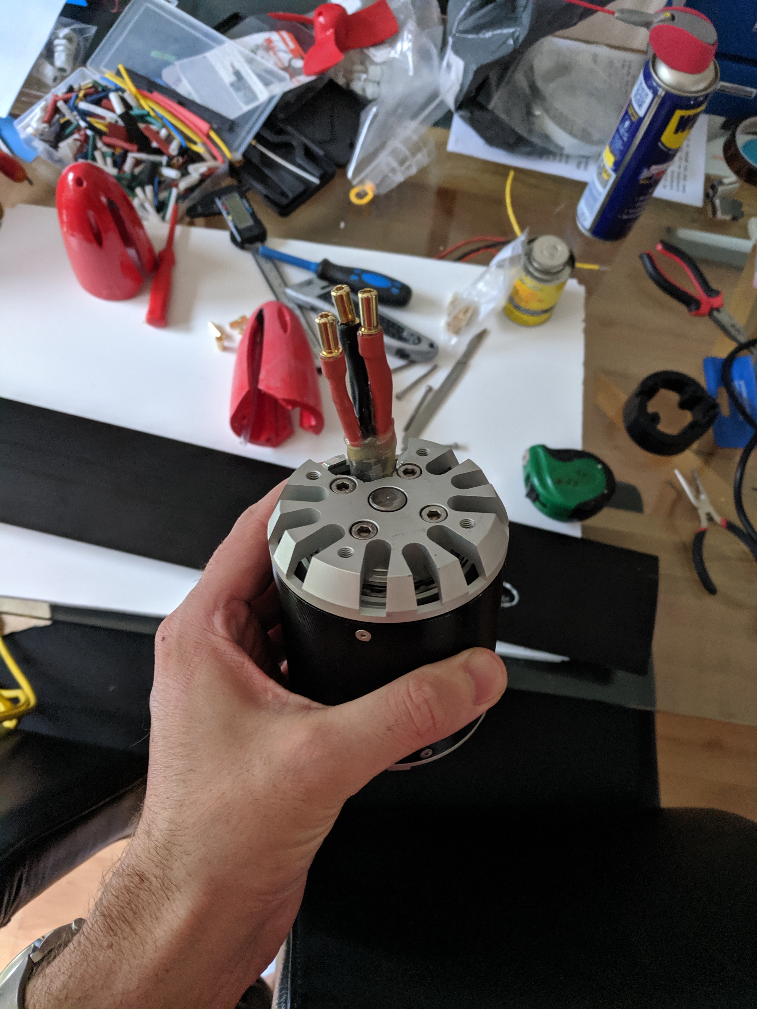
All reassembled and tested working well.
One note if I was starting from scratch again, I would make the leads out the motor shorter. So they are only just out of motor (just enough to allow some waterproof connections. Thus would allow more room in the nose cone for the cables. Also I’d have the cables in the forward cavity of the mast and water cooling tube in the rear cavity. Just to make routing easier.
I used the original bearings which I’ll flush out for this summer. Then strip it all down over the winter to check over / touch up and replace with stainless or ceramic.
The shorter shaft is a titanium one, funny material to work with. It can be scolding hot one end and cold the other barely 10cm away.
3 Likes
So I finally got all the pieces together today!

And dropped it in a hot tub to do a wet test.
So on the dry all is working as expected, but when in the water its having trouble spinning up the motor. See the YouTube video below.
I’m guessing either I have water getting into a couple of the phase cables,
Or there is a timing issues in the esc settings (Which is a Flier Boat currently set at 20 degrees)
The timing issues is the one I’m leading towards at the moment as when it does spin up it was running really well!
– Also much easier to change the esc settings!
Has anyone building a 80100 experienced this, or it anyone able to diagnose the problem from the video?

I often had not propeerly insulated wires connections, it never caused me motor issues (only tested in lake for the 80100)
i think my timing was 30 with the flier 300A ESC, is your motor 80kv ?
Frequency and timing on esc
For the motor , did you take off the coating on each wires before soldering? , you cannot just cut and solder , some coating are heat résistant , on my tp motor i had to hand sand each copper wires on each phase … (took me forever)
can it be the low voltage cutoff on the ESC set too high?
Yes 80kv and the ESC its a 300amp also. I’ll try playing with the timing to see what happens. I’m away this weekend so will update next week 
I don’t think it’s a low voltage, the Lippi’s are both fully charged. I’ll check though and may set the cell count manually rather than auto.
Yeah I noticed the wire coating but quite confident the connections are ok.
Btw, this forum is awesome. Loving the support!
Well if you don’t have not a good connection on each small wires you will loose potentiel « torque » and on load this can end this way …
frequency around 30 , timing 20-30 , test in water without / with propeller, progressive throttle …if still doing it , I will go with resolder after scrapping each wires
It is hard to have a good solder , even on my brand new sss motor , factory 8mm connector pull off after 3 unplug
As low voltage , it is more voltage sag on high amp: my battery drop 1,5v , my motor hits 90a ( limit set), just on full trigger , in the air and without propeller
So in water, voltage sag , current control ( test set in high) … ( if esc has it)
Ok, so tweaking the timing on the motor solves the problem shown in the video. I tried different combinations using the frequency start power etc but the timing was the main one. Setting to 25-30 did the trick.
I did also set the cell count to 12s rather than auto, but that was more because it was bugging me!
However, on a final test it stopped working again, and on inspection of the motor I found a couple of the small screws had come loose which is my fault for not using thread lock (I was holding off until I was happy with everything…)
But more importantly I could feel resistance in the motor. Hoping to use the stock bearing for now is not going to happen. 316 stainless bearing are on order for the weekend and will replace them before going any further.
First flight!
And a not so graceful landing😂
All looking good though. Need to tweak a few settings on the ESC and might try the two blade version of the propeller as the three has sooo much thrust!
I think the low voltage cut off on the ESC is cutting in due to voltage drop under load. It’s currently set to 3.2v per cell, but kicking in when only the top 10% of battery is used
4 Likes