is there anyone interest on building the motor with ESC, battery plus RF circuit in the same tube?
I like the idea o building an engine that can be charged and plugged on/off from the foil.
Since people can use their own foil and don’t need to cut the board and pass the wires in the shaft to put the ESC and battery.
I would like to make the circuit board with own ESC, RF 2.4GHz (combined with an own RF controller showing battery status and controlling speed) and battery charger.
I can make the circuit board with all elements included, but can someone mechanically managed to design the batteries needed, motor and circuit board on the same tube with foil attachment?
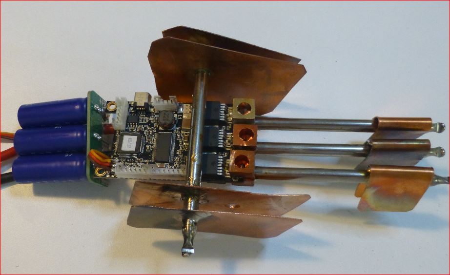
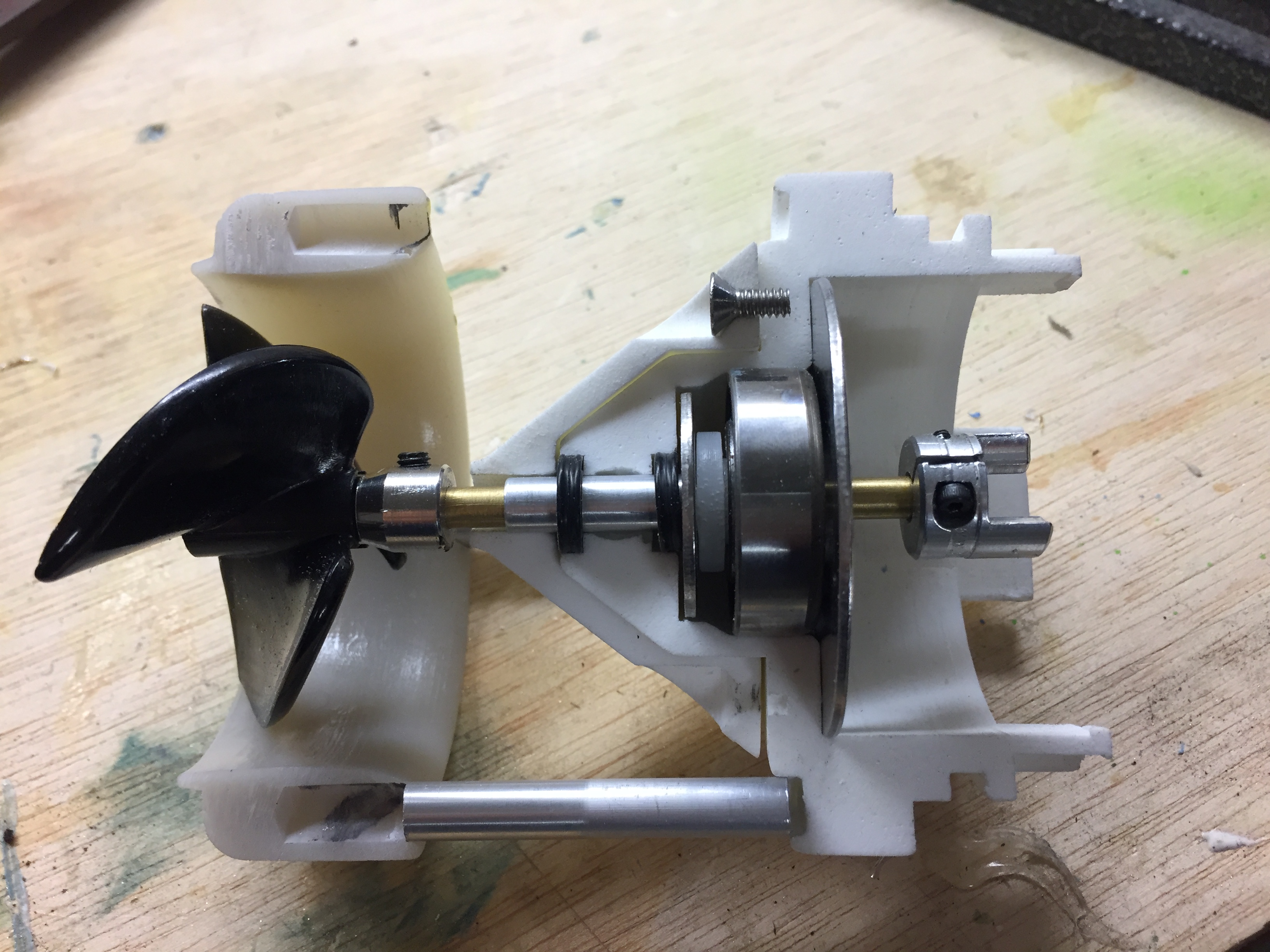
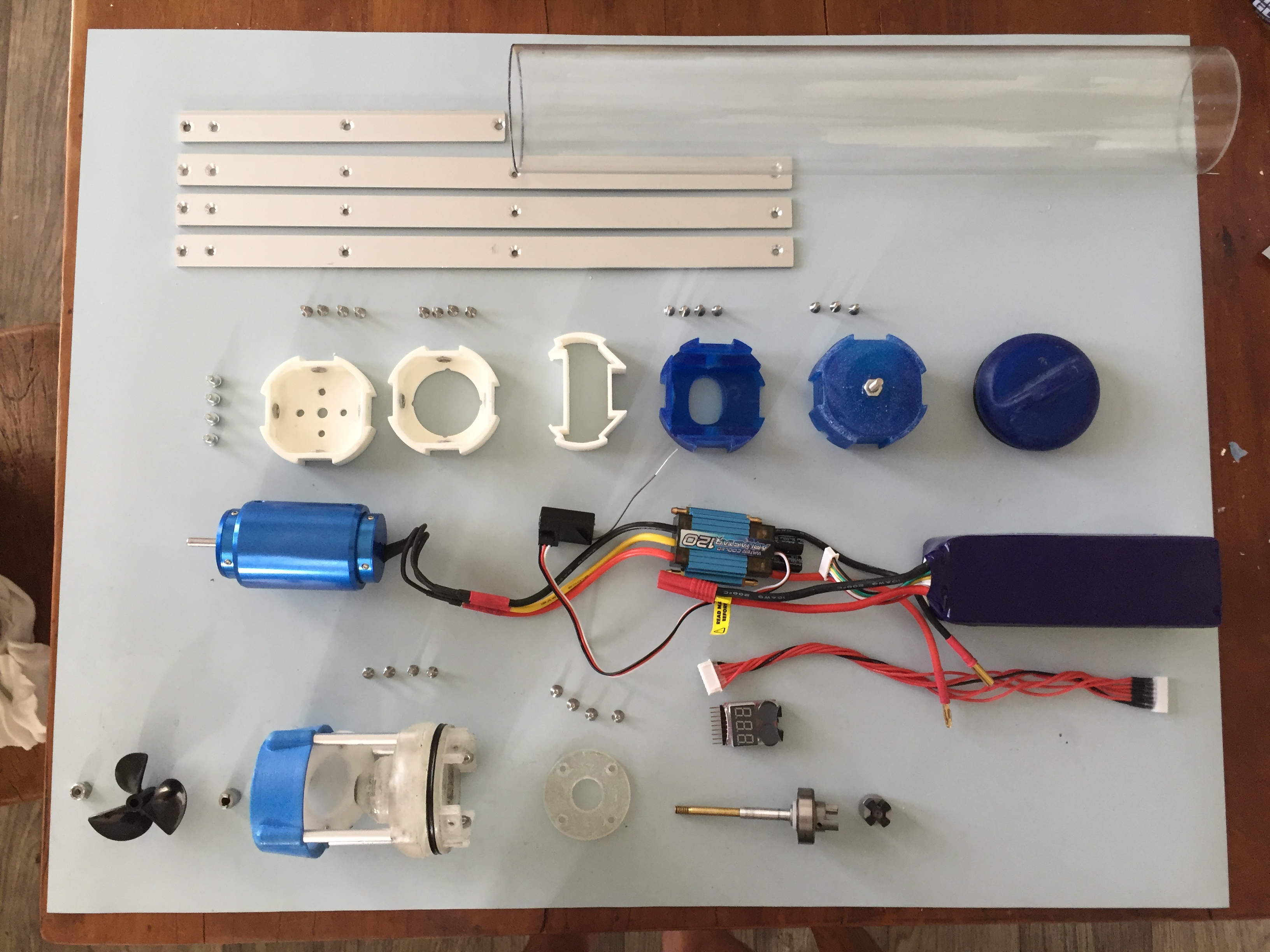
that was my first try… not successful for a few reasons:
you have less space to put battery, so if you want any kind of autonomy, you’ll need top efficiency.
the tube is under water, so 2.4GHZ will not work… you have to go down in frequency… RC subs uses 27mhz… but that’s very hard to find … and if you want to make it arduino based you can only find 300 something Mhz… that’s what i used and at best i went through 2 ft of water.
both motor and ESC were watercooled but without pump to save on space. The water pressure was picked up right after the propeller.
waterproofing is manageable, but heat management was bad… even with the water cooling. 12AWG wires were too small for the 100 amps needed to get 2KW out of a 6s… and the heat generated ended up meting connection point inside the Amp meter i used… i kept testing and i ended up burning my 120A ESC…
In the end, to be able to test, i had to put an extension to bring the receiver on top of the board to keep a reliable connection.
But my setup was not very efficient and i only manage to get the board moving with me standing on it, but way to slow to be able to get on the foil…
lesson learn: follow the KISS principle : Keep It Simple Stupid!
Current setup is direct cooling oversized outrunner… batteries and oversized ESC in the board.
i’m not saying it’s impossible, but with so many trade of, the end result might not be worth the pain…
it was a very fun journey though… all the parts were 3d printed then molded in silicon and casted with resin to make them stronger and more heat resistant and waterproof…
a few pictures below: (before i finished my arduino based remote/receiver)
So are you in?
Your setup is very cool and it is what we need to build.
I will check the RF to work under water, tunning TX power to be stronger and RX to be more sensitive with different antennas could be a solution.
I want to make an ESC that can handle double of power that is needed with 99% efficiency(lower temperature). This can be a little more expensive but less heat dissipation. The whole electronic with RF, battery charger and ESC will cost under 100$. The most expensive parts are the Mosfets for the ESC.
What do you think? Do you want to give a second try?
Ob’s: keep cables shorter as possible.
I had problems getting all of my stuff in the board. And I use two big cases. Not saying that it won’t work, but getting those 6mm thick cables in there will be hard.
There is 2.4GHz range extender that can increase the range by a lot and sub 1GHz RF ICs that can go up to 120km on a clear area. I think there is a solution for the underwater signal.
I like the 2.4GHz with Range externer better becouse we can use the phone or smart watch to control the board and also use a remote control with display.
that version is now just a “statue” in my living room… i might be able to use it to make some soup though… but i stopped trying to make it work (i wasted a year on it already… ). To make sure try 2 is working, i’m going way overpowered (80100 outrunner, 400A esc)…
and to be clearer on cost: the most expensive part is… time :), the second will be the batteries if you want significant autonomy, but with the space constrain of “all in one” that will be limited. However, i would advisable on thinking about designing an easily swap-able battery pack. i basically had to disassemble my whole think to change the battery… not an easy task on a sandy beach )
regarding the RF, it’s a matter of frequency, regardless of the power, the frequency won’t penetrate water… try to put you cell phone under an inch of water and see how it looses signal right away… the forum for RC submarines are full of good information.
i tried a 2.4ghz pistol style car remove that i re-packages to make it waterproof, keeping the orginial antennas, but i got absolutely no penetration in the water. I think tried a 75mhz remote, but the technology was so old with through-hole components that the board was way too big to repackage (and the remote needed 12v).
So i finally turn to homemade arduino based, first with 433mhz and then 315mhz… best penetration was with the 315, coiled antenna on remote side and coil loaded dipole on the receiver side. The tuning was amateur at best as i don’t have the equipment to do something more professional. I was getting around half a mile in air… but just a couple feet in water…
regarding the ESC, you might have a change if you do it yourself with better cooling… i was using: TURNIGY AQUASTAR 120A WATER COOLED ESC. i opened it after it stopped working to see what was burnt, and the water cooling is a joke… i’m not sure the heat could go from the electronic to the housing where the water was running… you might want to look closely at Benjamin Vedder’s work … creator of the VSEC that some people here are testing.
the motor was a TURNIGY AQUASTAR 4084-620KV with a watercooling jacket. I was thinking going with 6s was good to keep the RPM reasonable and compatible with the prop size i was using. 3-BLADE BOAT PROPELLERS D52XP80. That’s the only part of the setup that didn’t die
but 6s make it harder for the electronic as you double the amps for the same power compared to 12s…
finally for the wires, they were very short, that’s was in my mind one of the good point of the all in one approach… but 12awg was too thin…
Finally, I think @virus also tried the all in one approach and he had a very sexy battery pack… have a look on youtube. However, he’s now back to having only the motor underwater with a direct drive system, so i guess he also dropped the all in one approach.
It is quite that, what you are looking for, also explaining all the problems already mentioned:
RF has extra wire to top
Batteries need a lot of space
big tube will induce high drag => not that important for slow sup since drag rises exponentially with speed, so very important for you.
Mat is right, the range/penetration is decreasing exponentially by increasing frequency (you can compensate that with power, but it will also have to increase exponentially to maintain same range/penetration). So you need as low as possible frequency. On the other hand the size of the antenna will increase linear by decreasing frequency. Do you remember any RC Car/Plane from the 90s? Those with the folding telescope antenna? Those were 27 or 42MHz, you don’t want to go back there…
Can you explain how you will do that?
In my opinion you need a 4 layer PCB (if you run sensorless motor with 3 shunt amp control because of the noise) and a you will have a more or less complex design which alone would lead to a custom PCB made in low quantity => will eat up almost all your budget…
Hi @Giga
you dont need necessarily a 4 later for the job.
But even if you do you can get 10 peaces for 40$ in pcbway.com for example. Design and circuit is not complex at all but cooling the heat through copper area will take More space. There is a new Technologie like heat pipes that can also absorve the heat for high speed processors.l in the pcb trought via holes.
The circuit is simple:
DRV8323-> 4,2€ (60V Three-Phase Smart Gate Driver With Three Current Shunt Amplifiers)
CSD88584Q5DC->4,3€ x 9(at least 6 but 9 will make less heat dissipation, because the current will be divided in 3 per phase, the more the better)
bq78z100-> 4.1€(battery gauge up to 2 cells)
bq24725A-> 3,2€(battery charger, only need external power supply like 24V)
RF can be:
CC6540R2 is a 2 Core processor, one with cortex M3 48MHz MCU and the other is a cortex M0 with Bluetooth 5 long range connected to RF 2.4Ghz extender CC2592 with 22dBm more TX power.
Bluetooth 5 can go up to 1.5km because receiver is sensitiver.
Or a simple sub 1GHz RF:
MSP432 Arm Cortex M4 48MHz with CC1120 RF transceiver with -120dBM Receiver sensitivity.
Because the device will be under water, the RF in controller has to have higher TX power
and the RF on the motor has to more sensitiver. If you only want to control the motor but if you want to get battery status, the TX and RX will be on both devices the same.
Also choosing the right antenna will make a big improvement.
So that the mosfets don’t get over heated or burned out, the DRV8323 has an current protection watcher that can be programmed and once it’s over 160A it gives MCU the notification.
If the current is 160A and the time gets over 10s for example, the MCU goes to safety mode and waits until mosfets cool down (allowing low speed only).
The Mosfet you selected are 40V 35A types. 3 in parallel will max out at 105A without any reserve. The cooling must be very good, beyond what i know.
I tried to equip the VESC with heat pipes soldered to the Drain of the 7 pin Fets. I use one heat pipe for the high side Fets and 3 individual for the low side Fets to maintain isolation. The heat pipes have cooling fins at the end. I use a fan to circulate the air in the battery/ESC box. After 30-60 seconds the power drops, so its not the overall air getting hot, but the heat pipes still deliver too little cooling power which is annoying.
It would be nice to have the features of VESC, like real overtemperature control and real phase current control combined with a larger mosfet PCB which can be cooled better.
I think about epoxying the complete VESC and put it inside a fluid.
@PowerGlider
Thanks to checking the mosfet. If you want to use 18V battery, you can go up to 200A If you want to use 40V and have continuous current up to 150A than just add more mosfet in parallel.
Check the Texas Instruments new Mosfet technology here Power blocks | TI.com
The VESC uses irfs7530-7ppb and it has more power dissipation than the CSD88584Q5DC.
The CSD88584Q5DC is much better in term of power dissipation. Beside the Bottom copper pad you also have TOP copper pad that you can use to cool it down.
The VESC uses DRV8302 from TI to drive the mosfets but i would rater use the DRV8323S because you can digitally controll it. It also has 3 current amplifiers output to go to the MCU. If the motor supports HALL Sensors you can feed the DRV8323S with 3 sensors to know the motor rotation speed.
The Mosfet technology and mosfets driver are getting better each year. Thats why i would build my own ESC.
yeah in theory, you just need a MCU, some gatedriver, amplifier and some FETs. But I think it is a quite long way till you have something reliably working…
That’s exactly what the VESCs do, but with other DRV chips.
So I guess you are using 4.xx design?!
The D-Pack package used on both sides is really bad for heat transfer (since most of the heat is brought to the back side, so onto the PCB and against the otherside FET). All newer versions use Direct FET package and only one side with FETs, so maybe upgrading to Focbox, Vesx, Escape, Bbox or V6 is worth it.
I used a VESC-X before. I tried it with water cooled heatsink and also a large heatpipe CPU cooler mounted to the housing.In the end i tried small aluminium heat sinks glued to the individual Fets. The latter one had the best air cooling, measured by performance with D-current and slowly turning motor/prop in water. After some hours driving it destroyed one direct FET and thereby also small connections on the PCB. I had set the temperature by 10°C higher than recommended, so maybe its my fault.
I could not get more power through it than with the VESC 4.12 with heatpipes now. 2.4kW was the maximum, quickly dropping to 1.7 …1.3kW.
So the question remains if the direct FET approach using thermal pads is really a good way? The area to transfer the heat is really small with those direct FETs. Most of the heat will go into the PCB and indirectly through the thermal pad into the housing.
And there is another problem: The PCB traces and the shunts and also the capacitors heat up as well and need some cooling at least by forced air flow.
Yesterday one of the capacitors of the VESC 4.12 just popped after charging without any current flow. I wonder what that means? Is my ripple current too high? I will cut out the BMS for the driving current and install larger capacitors. Maybe i get better results then.
how did you attach them mechanically? I guess pressure is quite important if you use anything like thermal paste/pads.
well, years ago we made some fun by using some “high” voltage to let some caps plopp. But I guess if you were over the cap rating you would have had other problems at the main PCB.
But if you are replacing your caps anyway you might have a look here. Also he has a nice heat sink design for the vesc 4.xx (he uses 4.7, but that doesnt matter).
What cap did fail? I have 2 assembled Vescs (4.12 modiified) and use 5 low ESR 470uF input caps, I have not killed any of cap yet. I connect my batteries with a 2 Ohm precharge resitor now, as I killed a vesc once with too long PSU wires and no precharge resistor.
So you would advise against directFET Vescs?
A picture of the failure and/or your cooling soultion would be great.
No, i do not want to advise against direct fets. I only think it makes things more complex. There are several cooling concepts for transistors, some are going through the PCB and some do not. If you place all Fets on same side of PCB, you can have masses of Vias to the back side and you could cool them easily because you have a very even surface (if you do not populate it). This makes it easy to attach heat sink with a very thin gap, still electric isolating. The problem with miniaturisation is the missing area and cross section leading to higher current and thermal flow density. We need something more rugged, the current flow density through VESC PCB is very high, especially with version X. More copper for those long lasting current!
The caps were getting hot. That might be the failure. Overload by too high resistance and inductance of source might have led to an overload situation. The middle one of the 3 680µF popped, at cool situation with around 50V without any current flow, it was around an hour sitting in this situation while balancing. The charging power supply is nice and was off at that time.
For insiders: The problem about testing with D-current using VESC with motors slowly turning while having masses of ohmic copper losses is, that the Capacitors and the DC-link circuit are not tested. Also the switching voltage losses inside the Fets is not considered correctly. I estimate the real life losses of my VESC 100% more than in D-current test run. Additionally to the losses inside the cells, cables, fuses, BMS, relays.
What do you think about totally epoxying the ESC and keep it underwater? Might it work in terms of efficient cooling? I have doubts about electrical isolation capability of the epoxy on one side and resisting to thermal power dissipation on another side.
I have attempted something along those lines in the thread Direct drive outrunner with direct water cooling - #44 by Flo - Propulsion System (Motor, Gears) - FOIL.zone. I used a standard isolation pad (glasfibre silicone foil) to get rid of any conducting path between the pipe and the transistors.
So far this was working quite welll in air, but I hesitate to seal it up for underwater use. Making it servicable is hard. That’s why I went back to a more conventional watercooling system using pumps.
I used a two component gel, it is used as electrical insolation and it helps transmit heat to the aluminum case. And on the plus side you can remove it if needed, just keep the usb accessible in case you want to flash the esc.

 ). To make sure try 2 is working, i’m going way overpowered (80100 outrunner, 400A esc)…