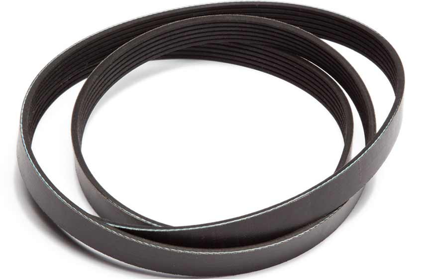
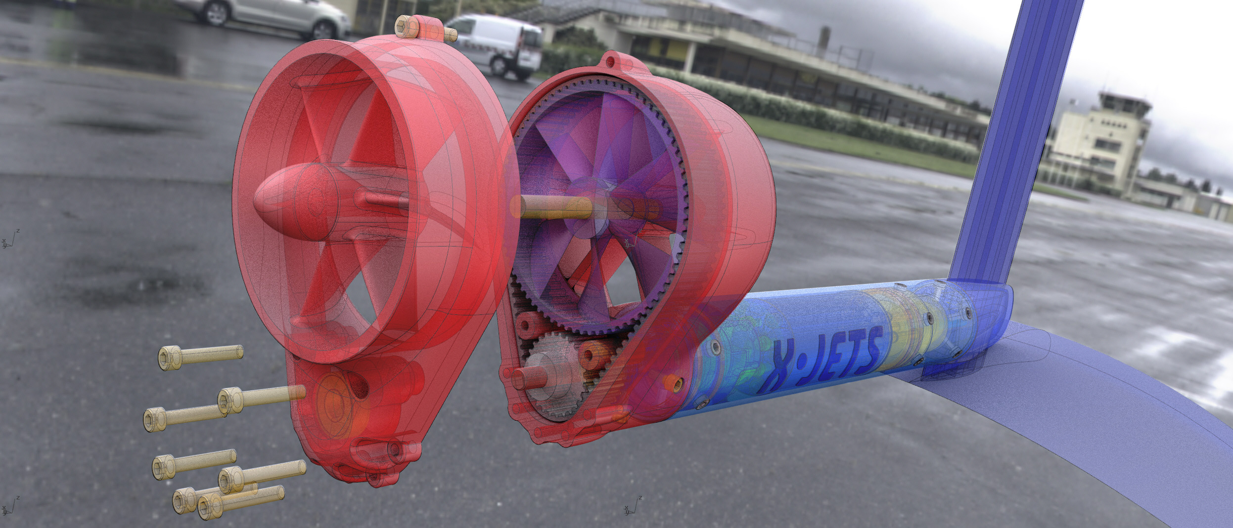
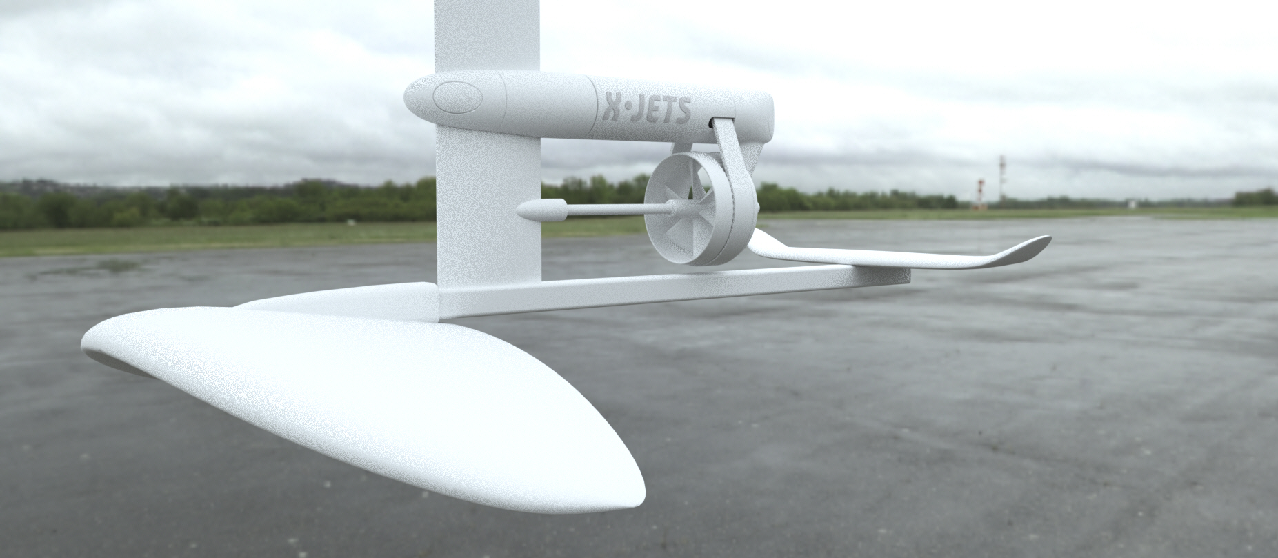
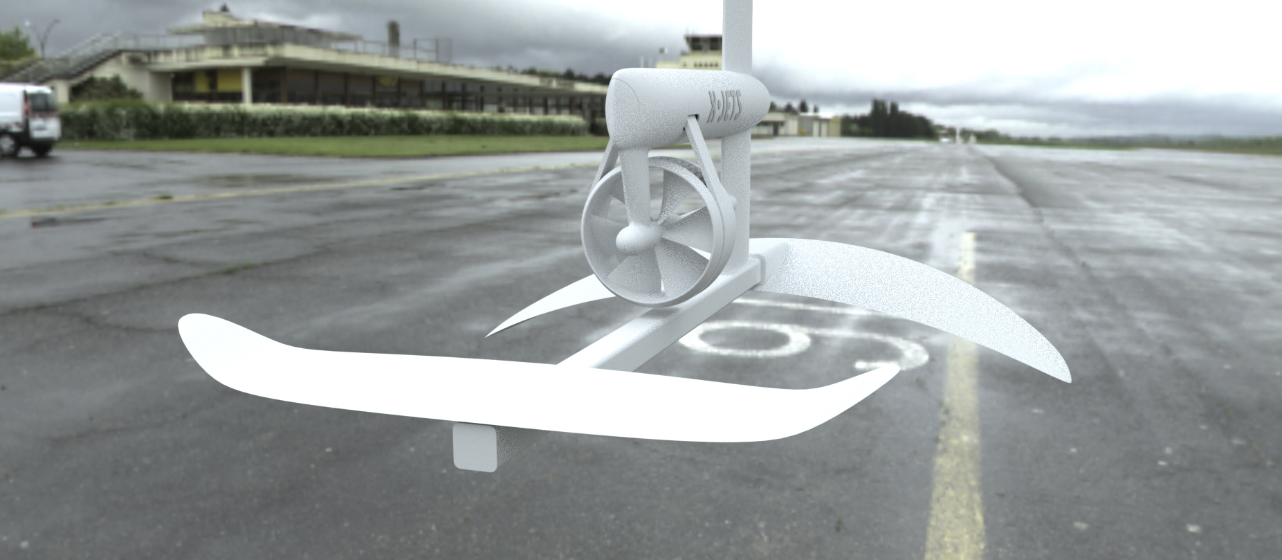
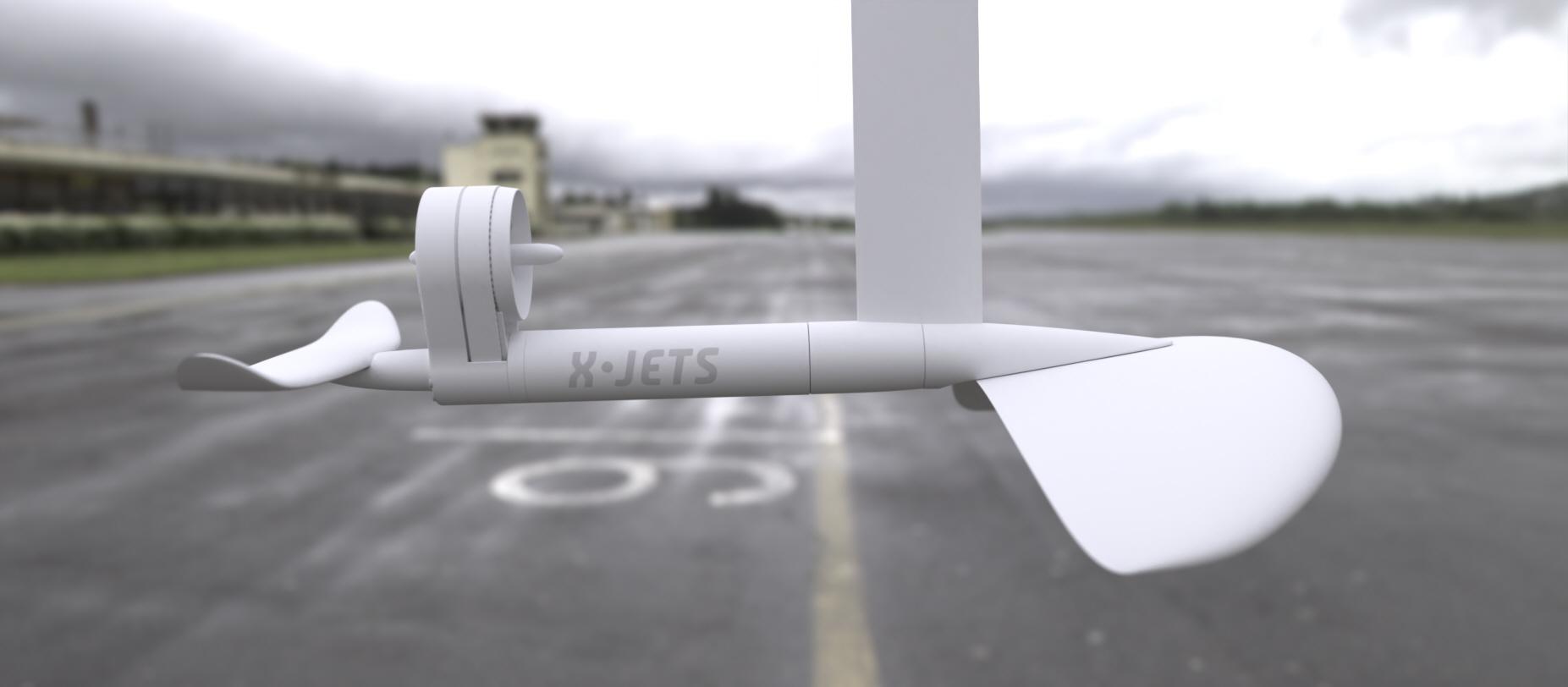
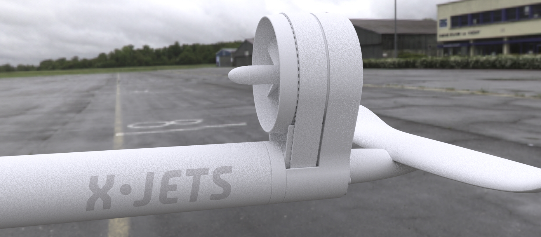
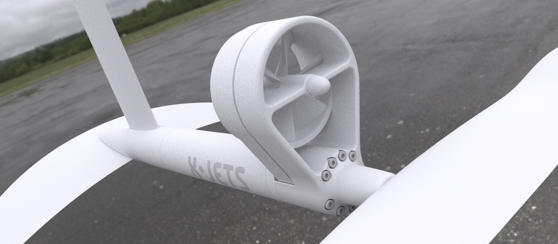
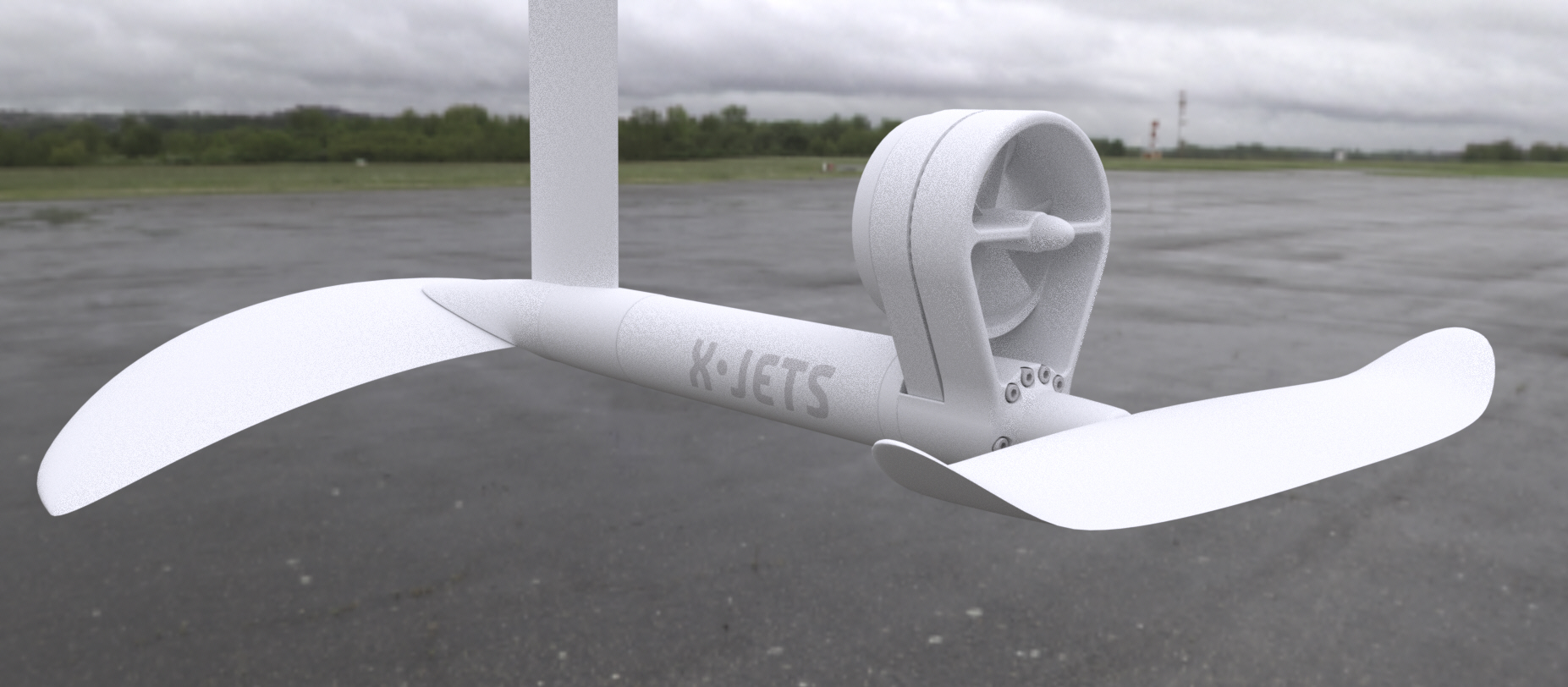
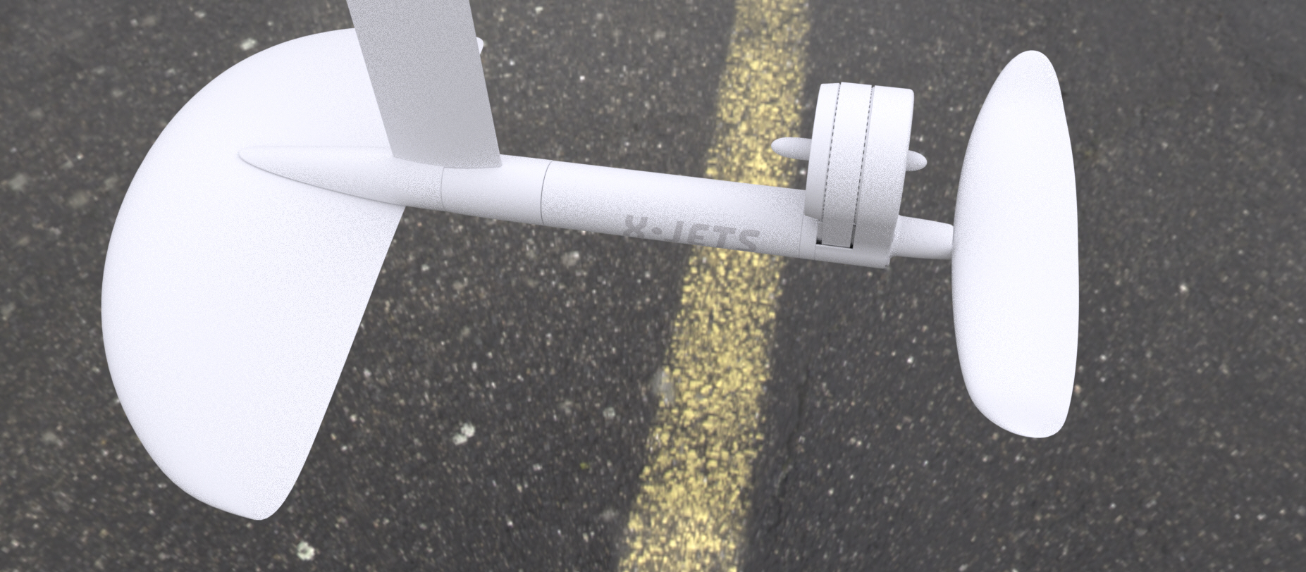
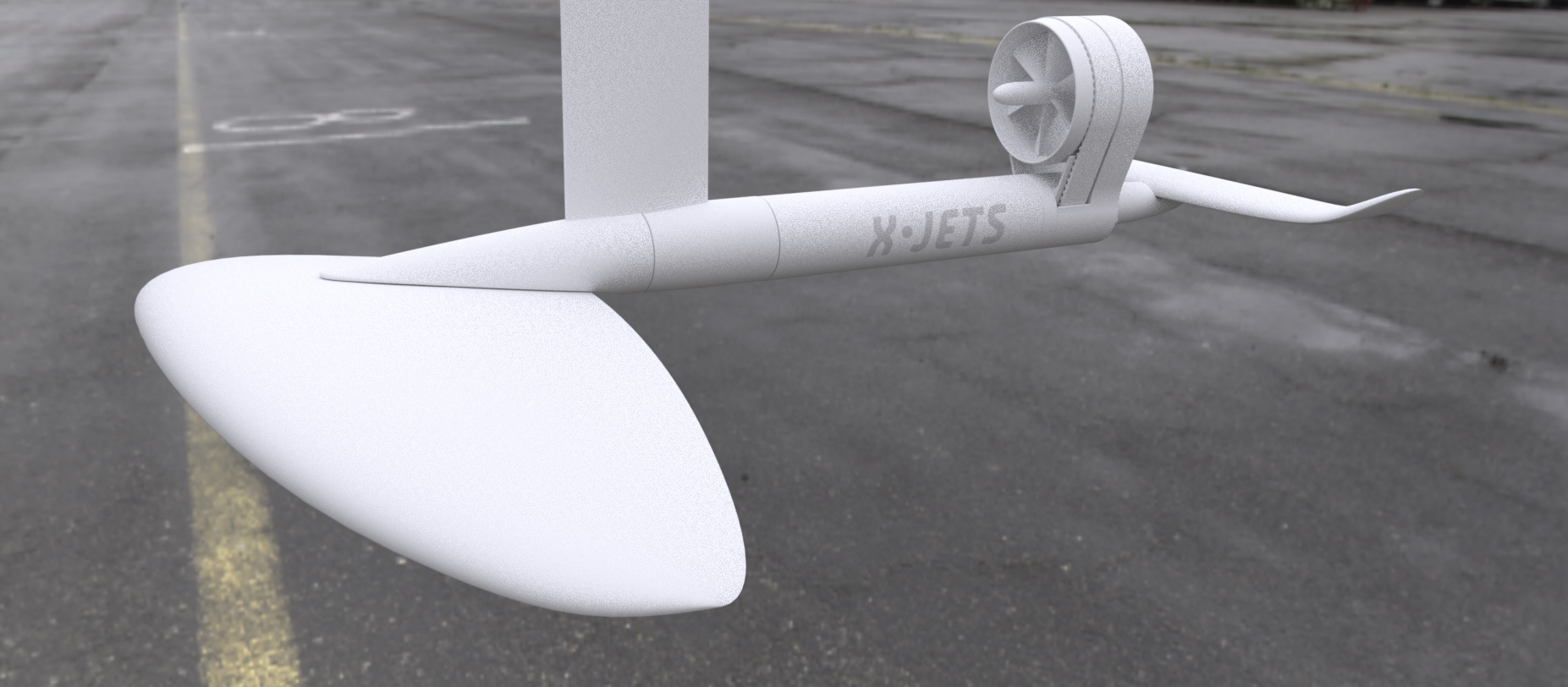
Still looking at the increased torque of reduction from higher RPM motor, but due to gearbox complexities, have considered a belt drive reduction. This is a concept of how this might be achieved 3:1 reduction. The belt is open in this iteration, and for this rendering, the teeth in the belt are not detailed, pulleys are actual scale and sized for teeth. It should be clear the approach from the renders. Decent protection on the front of the rotor with minimum flow interference. Downside, everything is spinning and may need a stator section in the rear to clean up the flow. Not as sleek as the torpedo pod family.
Very cool X-Jets!
That is a doable design though I’m, not a fan of so much open prop areas and also the added danger of the belt spinning to catch weeds, hair, clothes, body parts
Must say, your renderings and designs are really great out of the box stuff, keep up the interesting and educational work!
Very cool concept. It definitely creates extra drag but I do like how this has built in gear reduction. I wonder if you could get rid of that rear shaft support behind the prop and replace it with two struts that work as but shaft supports and belt covers. They could have an airfoil profile to minimize drag
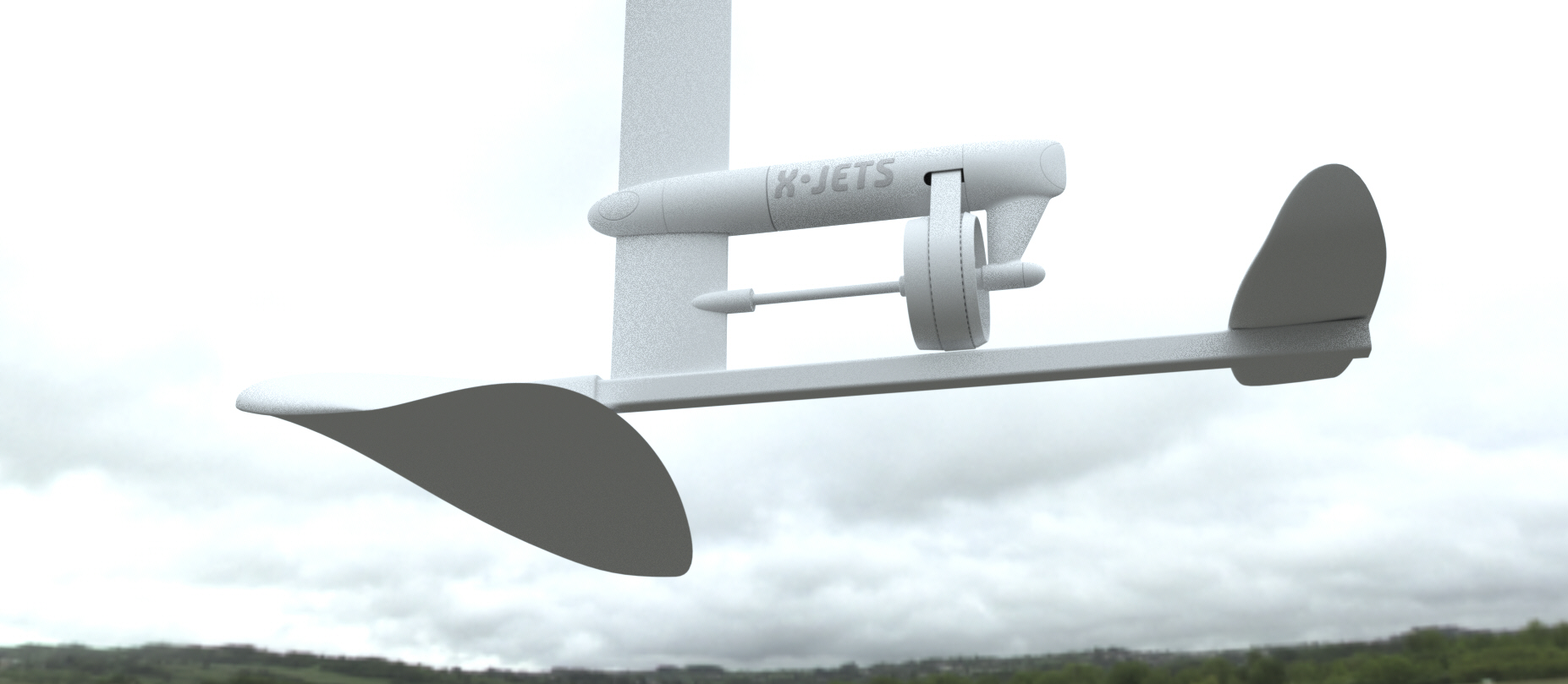
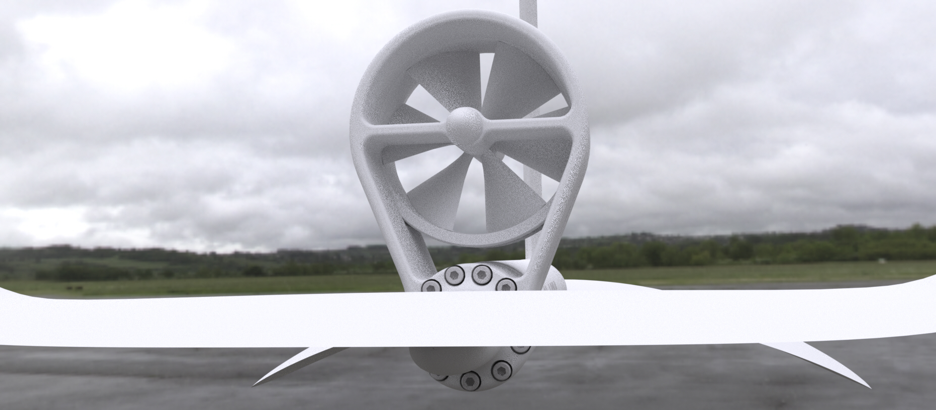
Some of the ideas were in the pipeline, but always inspiring to have someone else push it to the front. The biggest issue was maintaining the strength of the fuselage through the belt section, came up with a solution. The second leap in reduction was a one sided spindle mounting, that freed up the design. The belt is now somewhat protected, the next step would be to front shroud profile or fully shroud. A static intake shroud is possible. This is mostly roughed out functional geometry for CNC aluminum. Renders are screen grabs from the live GPU render display engine.
Nice, I like this!
have you considered using a gear drive instead of belt? The you can have the prop closer to the fuselage. Also, less drag from belt, and no belt vibration issues that may accurate do to water flow. But tolerances and such may be a problem Having the prop closer to the fuselage will also generate less moment on the fuselage.
maybe add support in from of the prop?, to make it more stable and accommodate belt tension. Also ease the strain on the axle and take up thrust more directly.
My first thought was to use gears, rim drive the housing like a starter motor, my biggest concern there was the small contact area between the gears and the hardness of material, stainless steel, that would be needed. Figured the likelihood of stripping out gears was pretty high given the power and load in any other material. I gravitated to the belt concept because of the dozens of teeth engaged constantly, and the slight tolerance for debris, and the ability to either print or CNC the impeller and housing from softer, POM or alloy materials. Distance center to center of the gears was based on an available belt length dimension for the first calculation. Having worked out the motor loading and spindle bearings now, I can revisit that dimensioning. The drive axle is getting supported on double bearings so load should be distributed well.
Supporting the impeller spindle axle from one side is just a question of shaft diameter and mount rigidity, less load on this impeller than a Vespa front wheel
Hello, nice pics, I like the idea, but I think that you should design a protection of the front side of the belt.
1 - with your actual design, you just have to increase the dimensions of the edge front of the propeller and add an edge on the V on the fuselage.
2 - if you modify the design to have the propeller between two bearings, the belt protection will come naturaly, with less rigidity and vibration problems.
So there is one thing that I see as a challenge. As the belt is going around it have to squeeze out water from between the pulleyes and the belt teeths. As we all know water is harder to move around than air. It will be very interesting to see how air/water drive is affecting the efficiency of the transmission. Maybe it would make sens to make the grooves deeper, with special channels or holes to give the squeezed water a place to go?
Looked around for examples of belt drives under water, does not seem to be very common. It will also be interesting to see how the belt keeps up with salt water, as I assume they are noe designed for this, altho I think that is a small concern in the bigger picture.
Tooth shape could be modified as there is a lot of contact, a less efficient tooth perhaps more wave-like is made up for by quantity. The teeth are naturally open on the sides, so plenty of space for the water to squeeze, but correct, it is an unknown right now. Salt water should be no problem with rubber construction, we use it in power hoses in hydroflight all the time, no issues.
@Flex spacing right now is due to the internal stack of plug - motor - coupling - bearings - seals - toothed gear. Turning that around would mean routing the wiring through everything. Supporting off the mast seemed to be more problematic for maintaining alignment then off the same axis as the motor.
@hotwireaddict Certainly looking at the shrouding of the belt. Construction-wise it is a little tougher to mount cleanly into the tube in front of the motor, and seemed cleaner to have a rigid enough axle from the back only, we’ll see.
Squeezing out of air is one reason why cars are so loud in reverse. Reverse gears are not used very often, so car manufacturers put in straight gears instead of helical gears to save money. Helical gears can push out the air gradually from in between the teeth.
Like your design. Maybe it would be possible to attach the toothed pulley directly to the motor shaft to shorten the over all length of the drive. You might need a longer shaft and it will be harder to fix the propeller unit to the tube. The force on the parts linking the tube (motor) and the Propeller will be quite high I think.


 Having the prop closer to the fuselage will also generate less moment on the fuselage.