Any interest in a custom e-foil ESC?

Tested a single board today to overtemp cutoff. 100A to a single switching board with no cooling takes about 10 seconds before the overtemp cutoff kicks in. The important part is that the overtemp is effective.

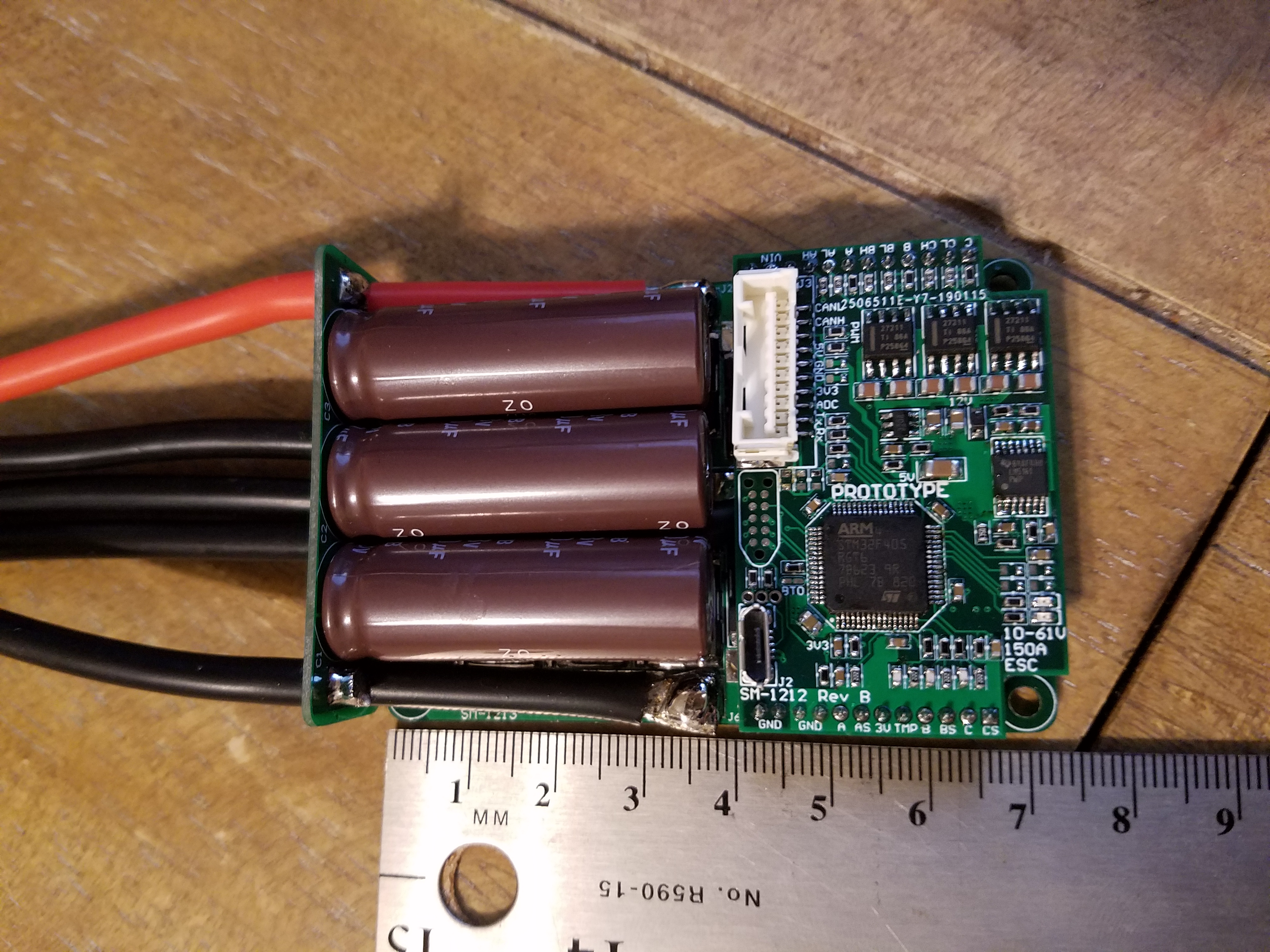
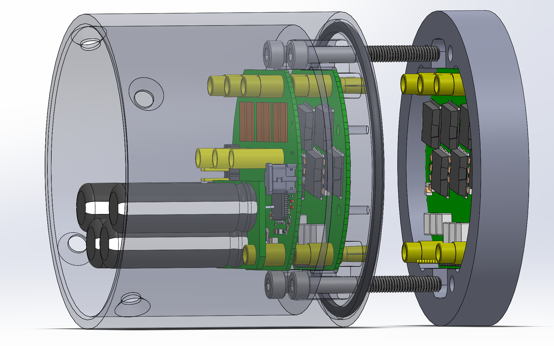
The switching boards are stackable, so that means current capability is as high as the number of switching boards. Each board can do 75A continuous, peaking to 100A for 10 seconds or so. The design is based on the VESC6, so it makes sense that the performance of 1 switch board is similar.

I would like to do a beta test, if anyone is interested. This would be a limited number of production modules for technical/power users (thatā€™s everyone on this forum), with the goal of finding any deeper bugs before mass production. This is also an opportunity to test the switching boards to their limits in water and see if my ratings are too conservative. The price for this run would be 300 USD for the logic board and first switch module, and 125 USD for additional switch modules. price will get cheaper if I can get ~10-20 people on board

Specs (itā€™s basically a VESC6):

  • Voltage: 10-60V
  • Current: 75A continuous motor phase current per switch board. 100A peak for 10sec, 10% duty (1 switching board)
  • Current control
  • Configurable RPM, current, voltage and power limits
  • Output Power to Controller: 5V .5A
  • Control source: PPM, Analog, I2C
  • Communication ports: USB, CAN, UART, (RS485 with jumpers)
  • Separate throttle curves for acceleration and brakes
  • Motor revolution, amp hour, watt hour counting
  • Real time data analysis and read out via communication ports
  • Adjustable protection to prevent blowing the electronics or battery:
    ā€‹ - Low input voltage
    - High input voltage
    - High motor current
    - High input current
    - High regenerative braking current (separate limits for the motor and the input)
    - High RPM (separate limits for each direction).
    - Over tempertaure (MOSFET and motor)

I canā€™t afford to make them if no one wants to buy them, so please send me a message if you want to buy one at this price, and I will get them on order (after I order its 6-8 weeks for delivery). Once they get here I will set up a web-store where you can pay for them, and hopefully receive them shortly.

1 Like

Nick

I like the idea of sealing the ESC in an aluminum can. I think in order to imporve, this can may be filled with high dielectric constant oil so the cooling will be more effective. As it is now, I am affraid that the contact between the heat generating components ( FETs ? ) and the cooling media (Aluminum can wall and sea water ) will make the cooling less effective.

Thank you for sharing this !!

Hovav.

Very nice job on designing those boards!

For me personally 425$ is a bit too pricey and I would also fear to loose or destroy motor + ESC in a single ground contact, or - more likely - have water ingress as result of a crash and fry this expensive ESC.

Good point. I got about .6K/W to the outside with .25" thick aluminum backing. I guess that could be a little high? Itā€™s still a 3D model so its simple enough to add more aluminum for better conductivity. Could also cross drill the heat sink part. That would keep things ice cold.

Sorry Benjo, low volume pcb manufacturing is unreasonably expensive. I donā€™t have enough money to make these boards either. :sob:

If I can get more people on board, the price comes down by a lot. All I can do is ask around to try and find help. Perhaps you have a rich friend who is into watersports?

1 Like

I hope you get the support you need to get these in to production. Development of direct drive 80100 motors has been quite interesting on this forum and your work with the electronics is quite impressive to me. Mainly because its well beyond my understanding. Great work and contribution to the forum. I hope it works out.

I understand that.
I assume you are not only having the PCB produced but also have them assembled? Maybe it would make sense to solder 1-3 units yourself and sell them at cost to reputable members of the community that can test them. I would assume the raw parts price including PCB somewhere in the ~150$ area for logic + one switch module? That would be more reasonable for a blind buy. I hope this doesnā€™t sound disrespectful or something, I just want this to work out :slightly_smiling_face:

1 Like

Hi @nickw1881,

  1. I think it is super professional design
  2. Im not sure I understood how the cooling is done in terms of heat dissipation from FETs towards the metal outer body and then to the water. Is there any physical contact between FETS and the tube?
  3. Now days there are thermal conductive filaments come up can it help to dissipate heat? Do you think it makes sense to make a package to guide the heat outside?
  4. Since the ESC is very close to the motor then the power cables will be about 1-1.5m long, which requires appropriate power end caps. Is it taken into account?

I would consider buying, what is the limit to the number of switch boards you can use before you overheat the FET drivers? Impressive design!

@benjo the boards I am using now were done with a batch prototyping service and assembled on a saturday by me. 5 logic and 5 switch boards bare (pcbcart.com): $200. Materials to assemble two logic and two switch boards: $600. Amazingly, it is cheaper to have boards fab and assembled in china than it is to buy just the materials in America. Also the thermal performance of a proper spec board will be too good for me to lead free solder with an iron and a heat gun. I could barely make the crap spec prototypes with tin/lead.

@Antonbit @hovav Here is my heat math:

  • The ā€œhotā€ part of the silicon in the FETs is bonded to the metal drain on the bottom, which is soldered to the board (.2-.4K/W datasheet)
  • The board has 130 epoxy filled plated over thermal vias under the drain of each FET with 1oz (1.4mil .036mm) copper plating in them (.4K/W). Sources also have thermal vias, not counted.
  • The switch board is bonded to the back of the can with thermal epoxy and secured in place with screws (~.1K/W).
  • The heat is transferred to the outside through the thermal conductivity of aluminum. I have drawn .25" thick aluminum, 1.4" between the slots, and 1.5 radius (.5K/W a fet, so 3K/W for all fets)
    The outside of the ā€œheatsinkā€ is the outside of the thruster in the water. The water is kept outside by the face seal o-ring.
    Die temp for any given fet assuming they all are producing equal power 3.8 x P + Case-water junction temp. Example: if each fet is producing 20W the die of each fet will be 76C+temp of case-water junction.

Concept pictures:


Possible options to improve thermal performance is
#1, thicken the aluminum
#2 cross drill the sides of the heat sink with 3mm/.125" holes. That would turn it into a ā€œwater blockā€, but with no need to pump the water. Itā€™s a little more complicated manufacturing (3rd milling operation) but it sure would keep things cool.

@jakebarnhill1 I am confident it will work fine with 3 switches. I donā€™t know what new problems there might be with 4 or 5- could be just fine. Gate drivers are way overbuilt. The power connections in and out, and current sense circuits will hit their power limits before the gate drivers and gate drive power supply have a problem.

Nick

Itā€™s been a long time since I did the undergrad course in heat transfer so I am a bit rusty but I get your point. bottom line you think there is good enough heat dissipation ? As I said before, I think you are doing an awesome job here !

I would like to offer some help. I was thinking - do you know this company : www.nano-di.com ?
They are a PCB rapid prototyping 3d type printer and I am a good friend of the CEO. Please take a look at their site and if they can produce the PCB, I will ask them to do it hopefully for free or if not I will ask them for a quote. I guess you will have to send me the GRBL files for that.

Please let me know.

Thanks
Hovav.

Ok, interesting. I was under the impression that you can build a VESC 6 by ordering all parts from mouser and soldering it yourself for around 100$ + connectors. What makes it that expensive for you? I know you have a special design, but component wise it is still a VESC 6.

Isnt it a bit early for a public beta? I would really advice to do some more testing before selling.

Also, how is the current sharing between the switching boards? There is no way that the current sharing is equal since the board further away from the control logic sees higher resistance than the one that is closer to the connections.

It looks like the gate drivers are on the control board, how did you size the gate resistors and accept a range of fets in parallel? This is normally very challenging in switching power electronics design (you will either be switching slower than needed or overloading the gate driver).

How is the temperature monitored for the different switching boards? Do you detect max temperature for all boards? Or just the case temperature?

These are just a few of the major thing that jump to mind. Donā€™t take my comments to harsh but from my opinion it is to early to sell.

2 Likes

@JTAG great points. I need help testing in real world conditions. I would never ship boards that I have not bench tested to advertised spec. I have already tested my prototype to the limits of my ability. I cant test it any harder by myself. To your points:

Power sharing: this design cannot possibly share power perfectly, as you noticed. But it doesnt need to. Part of this is rating the boards conservatively. 100A peak 75A continuous is well below the 300A rating on each fet. Even if they do not share perfectly, no single fet can exceed its ratings.

4A gate drivers with 4.7uF bootstraps. The 12V gate drive power comes from a 1A dc/dc. Theoretical max peak drive currents are <=1A with chosen gate resistors. The driver circuit is in no danger with 3 switch stacks. I dont recommend using 4 or 5 switch stacks, though its probably safe with diminishing returns.

Gate balancing: gate resistors are per-fet, which you can see on many esc from kde, castle, hobbywing, etc. Some fets are going to switch slower than others. Its not about everything being perfect, its about everything staying within its ratings.

Temp monitoring is only on the closest board. The vesc software allows 1 fet temp input.

@everyone I think I have an idea. A large portion of the $425 was to cnc the round, underwater aluminum in-thruster heat sink parts. What if this isnt strictly for underwater use?

If I shipped without the aluminum, people could do their own heat sinks in the board like they do now. We are all DIYers here. If people can make a whole efoil, they can make a heat sink or water block by cross drilling a piece of 3/8" (10mm) aluminum.

I could get 10 logic and 20 switch boards for $100 each. If I sell near cost (this was always the plan), that puts the price at about the same as commercial escs: $200 for a 75A and $300 for a 150A 14S esc. As mentioned previously, those ratings are continuous and conservative. If I can get the price down cheaper for the beta I will do it.

This would let people test in their existing rigs, without risky thruster mods and undersea electronics. I can handle the $800 cost of the stacking pins. Does this seem more reasonable?

Edit for clarification: Itā€™s going to take months to actually get everything here and built and bench tested. I am trying to establish whether or not this is something I should do, or if just leave it alone and get high. We are talking serious money (to me). If 5-10 people say ā€œyes we like itā€ hereā€™s the game plan:

  • Iā€™ll front 4k USD to make a batch of spec boards and come back in a few months when everything gets here
  • PM a 2-3 well known community members and send them some boards to play with.
  • If we get good reviews, then Iā€™ll open up a simple web shop to offer some of the rest of the batch that Iā€™m not keeping for myself.
  • My hope is that the boards are useful to others as well as me and I make some of my money back so I am not out all 4k.
4 Likes

@nickw1881 this is sick, the ESC is the only thing Iā€™m affraid of in this project because it ainā€™t cheap and it ainā€™t durable most of the time. But youā€™re gently developing one especially for us, how can we not be stocked? As I donā€™t want to burn 300$, this a great alternative, please keep it up!

I want a single power board with logic and capacitor board. How is the progress? Do you have more test results?

Iā€™m getting some parts made for a high power test. Iā€™m gonna make electric outboard motor thing with this ESC and an 80100 motor and put it on a little boat. Itā€™ll be a month or so.

1 Like

Hi Nick Do you have any news regarding your ESC ?

Sure. I have been talking a lot with @PowerGlider recently and he convinced me that I should ditch my round design and switch to a square one in the 50x80mm form factor that is recently popular. Iā€™m American so its going to be more like 50.8x80 (2x3.15 inch). The goal is the 48V, 120-150A range with FOC operation. Users would be e-foils, e-skate, bikes, and scooters. Here is the last rev:

It had way too much noise during the switching operations, possibly due to some bad layout choices. I ordered a new rev today, hopefully I learned the correct lesson and fixed the noise. As soon as I have some positive test results I will let you guys know and post a video. Next week maybe.

Funny enough this form factor is actually more compact than original my round design and will fit into a smaller pressure vessel.

6 Likes

This is great design. It has a flat back packed with copper. It can be mounted to any flat surface. These can be watercooled. I am working on designs with PR158 heatsink to be passive watercooled starting with a simple battery box. A lot of design variations are possible with this concept of through cooling the PCB. I got some high temperature epoxy resin to isolate the cooler for my special setup with some glas fiber to be applied to the untouched eloxied aluminium surface.

3 Likes