I finally got enough time to dial in the gate resistance and timing and run a proper test. Dunno what I was seeing on monday evening but now I have video of the ESC/motor/prop working from 45V/54A input up to touching 50V/60A input. Thermal camera shows less than 60C. Right behind a giant propeller.
Unfortunately the VESC software seems to be limiting itself. I started the video at 45 ish volts and ramped up the throttle to 95%, then turned up the power supply voltage to 50 and you can hear the controller throttling back. I’m sure its some setting in the software, I could use a little help to find which one.
Current limits in hwconf 4.10 and board.h are set to 200A (sensor can only sense up to 165A)
max erpm is set to 200,000
max voltage is set to 61, sensor can only sense up to 61.8
no faults are reported
power supply current limit is set at 150A input (and its the kind where it backs off the voltage, dont see that)
haven’t messed with the timing advance, not sure what the process is for messing with it.
Overall I am very pleased with the performance. I think it will hit my design goals. For sure I need to make a better dyno that is not a loud whirlyblade of death.
I think it might still be the absolute max current setting. In my first tests with a standard 4.12 version which has 160A max current I found a similar behaviour. I was previously running with 80 to 90 A motor current. Then I disassembled and reassembled the setup. The reassembled setup had 1m longer phase wires, but I am still not sure if this really was the cause. It just seemed to loose sync after a while at full power. It just stopped completly. What I did was raise the abs max current setup to the max 160 A and it was fine again until I tried to push 140A motor current. Then I had to switch to shunts with half the resistance and increase the current limit again. My theory is, that the current spikes are higher than the avarage motor current and thus you hit the abs max current fault. You should be able to spot this error on the vesc console tab with typing ‚faults‘ as a command. This shows all errors since the startup of the vesc in vesc tool. The abs overcurrent fault is hard to spot otherwise as it is very brief and clears itself.
There are several binary files for each hardware version in the VESC-Tool and also the BLDC-Tool available. Unfortunately the one for 4.12 is only available with compiler option “No HW Limits” or 0.0005 Ohm shunts. To overcome this problem you need to compile the code with modified header files.
Here are the values you need to modify, found in hw_*.h:
#define HW_LIM_CURRENT -120.0, 120.0 #define HW_LIM_CURRENT_IN -120.0, 120.0 #define HW_LIM_CURRENT_ABS 0.0, 160.0 #define CURRENT_SHUNT_RES 0.0005
I was not able to compile and download it for the moment, but i work on it.
The great problem with DRV8302 and also DRV8301 is the low gate drive current.
I just measured the gate voltage and phase voltage of my newest setup with IPT007N06N and it takes the high side 250ns to switch off, than the gate voltage at the low side FET rises within 100ns.
This means, additionally to the switching losses, we have diode losses, because of the long dead time needed. So the losses in the Fets are much higher than ever expected. The conduction losses are around 3-10 times lower.
Also the concept with only two shunts is bad, it makes it necessary to limit the PWM to 95%, so you always have switching losses, even when you could have 100%. Benjamin developed a sort of variable switching frequency you can adjust in the VESC Tool in BLDC Mode under tab advanced. It was introduced with the justification to enhance the sampling quality. I think it should have been used to reduce the switching losses as well.
My conclusion for the moment: VESC has its limits which has little to do with the power fets used. The driver DRV83xx are much too weak to drive such Fets in the power regions they were meant to be used. This also explains why air cooling is failing so badly. Also with my newest setup the max power of 2.4kW falls within a minute to 1.8kW and after everything is heated even lower. Its a drama.
At nick:
Which gate driver are you using at the moment? Can i buy a VESC from you?
I have multiple compiled versions, if you want something compiled just send me the changes or a zipped/ tar archive of the source folder and I can compile it. I just use a PC with ubuntu linux on it. This is much easier to configure as build environment than a windows machine.
The gate drive is really the weak part otherwise just installing more fets would be easy. Three phase shunts are the better way, too. That‘s why all new versions of the vesc use it.
2 or 3 shunts are only needed for FOC, for BLDC also a single low side shunt would be enough to control the phase current because the duty cycle is known.We do not need this super fast reaction time for phase current limitation for our traction purpose. Even the eskaters do not need it. It is only needed for servo drives and there you use sensors additionally. For BLDC traction with low speed motors like we use, the measurement interval could be much longer, i will try to limit the maximum switching frequency and see how it works tomorrow. If you can compile with these changed lines
in hw_410.h that would be great.
Afterwards in VESC tool you should limit the maximum switching frequency to 5kHz, otherwise you should not change the #define HW_LIM_DUTY_MAX 0.0, 0.99,
because the measurement becomes too noisy.
I changed the maximum switching frequency to 15kHz, it seemed to work. Than i went down to 5kHz. Now i have a DRV error. It is still present after going back to 40kHz. Be careful!
I just read that the control loop is completely dependent on the switching frequency. It is always half of switching frequency. It seems to me the DRV lifetime is dependent on the software control loss. Benjamin stated in a thread from 2016 he has hundred broken DRV.
Been learning a lot about the VESC and how it works.
My VESC was losing commutation at high voltage and high current partially because I have too large of current sense resistors, and possibly also too short of a delay after the switching event before the measurement is done (required to get to 95% throttle). The current sense saturates the ADC and it can’t keep track of the values anymore.
Running 95% throttle at 20kHz PWM means there is only 2.5us to sense current, including ~1.5us switching time. Add in some oscillation from switching too hard and an algorithm based on current sense isn’t going to work very well. My single-board VESC is probably going to be limited to 80-90% throttle when we are running 12 or 14S batteries. This is a limitation of the VESC 4.x.
I switched the current sense resistors to 3uOhm, and the VESC seems to run OK on my desk. I’ll get some videos later this week or next week when I finally finish making a dyno. Hopefully I can demonstrate 70A motor current for longer than 2 seconds.
What I have learned (and Vedder has been saying for 2 years) is that there are some major limitations to the VESC4 design:
current sense sampling limited to switching frequency, so in order to run well, you have to switch at 40kHz
can only sense during low side synchronous rectification
throttle is limited by 1 and 2
have to assume phase 2 based on phase 1 and 3
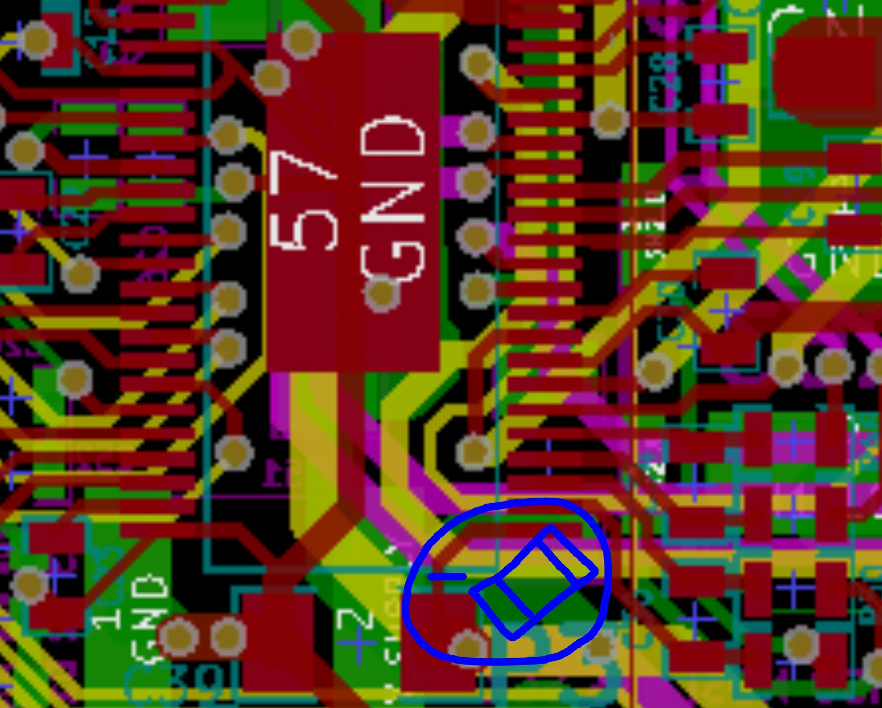
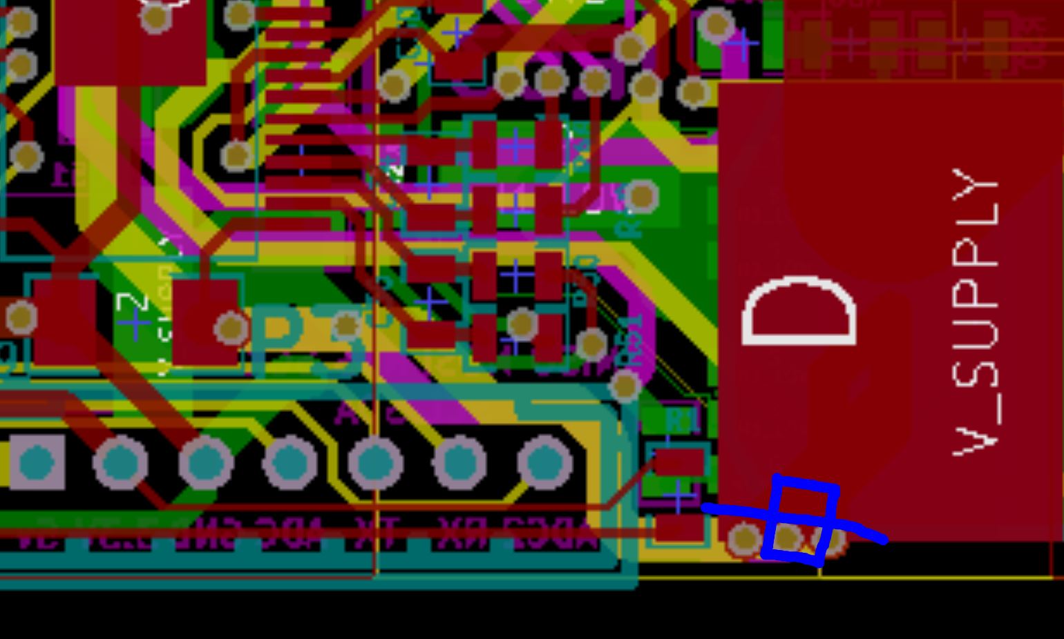
These issues force you to switch at 40kHz, which then forces you to switch hard, which causes large switching transients. Those transients are probably what keeps exploding the DRV8301’s when you run at 12S. VESC4 makers should put a ferrite bead on the DRV8301 PVDD1. Or slow down the switching with larger gate resistors and increase the layout area to give the fets a chance to dump the extra switching heat. If you have blown a DRV8301 (and I know all of you have) and are putting on a new one, you should cut the trace going to PVDD1 (pin 29) and put a small 0805 or 0603 ferrite bead in there. https://www.digikey.com/product-detail/en/tdk-corporation/MPZ2012S331AT000/445-1569-1-ND/571899
Your design is cool! I have tought about making my own design of a Vesc but always postponed it because of the effort. I mostly wanted stronger drivers and more fets which are all on one side for easier cooling.
I would like to add that I seem to have less trouble with my vesc’s drv8302 (that’s the chip the 4.12 vesc uses, the 8301 is for version 6 I think) than others, despite the fact that I have pushed my modified 4.12 vescs to more than 100A with 12S input. I just use good low ESR Capacitors (6 times 460uF currently) very close to the input and I have overvoltage protection diodes across the two largest input voltage ceramic capacitors on the board.
I had the trouble with the current sense resistors, too. The original vesc is limited to +/-160A current sensing and as current peaks exeed this the motor sometimes ‘lost sync’, i.e. suddenly stopped. With currents of about 90A average. I overcame this after @PowerGlider made me aware of my issue with the losses in the 1mOhm sense resistors. I then switched to 0.5mOhm sense resistors, got ±320A mesurement range and this solved my issues.
The packaging of the vesc4.12 is still really bad with added watercooling though.
I made some measurements with 0 current and the DRV8302 is a bit noisy. I measured with oszi in AC a swinging of the outputvoltage of SO1 and SO2 up to 40mV. That corresponds to ± 8A. I can see similar output on the VESC Tool ±5A. I compared with other VESC i have, the never used VESC with default.bin shows ±2A, the heatpipe monster i built shows ±4A with 0.0005.bin on the old BLDC-Tool.
As i am using BLDC mode it should not have dramatic effect on the commutation quality, but only on the current limiting, but maybe i am wrong.
This brings me back to the question, if this shunt measurement with 95% maximum dutycycle is needed at all. In BLDC mode, a single shunt in the supply line could work better. Of course also here some synchronisation is needed, but it should run up to 100%. In BLDC mode you can control the current consumption at high RPM without PWM, just by shifting the phase and would create similar behaviour as field weakening. By this the switching losses could be avoided at most, instead of 20-40kHz you would have something like 400Hz. For our purpose this would be perfect, as the power and current typical increases with RPM dramatically. Additionally we could reach higher RPM with a kind of weak topping with constant power.
This also would ease the requirements for the capacitors lifetime.
In this mode a variable switching frequency would still make sense to minimize switching losses and maximize PWM resolution. Maybe we should adress this in the VESC forum? What ya think?
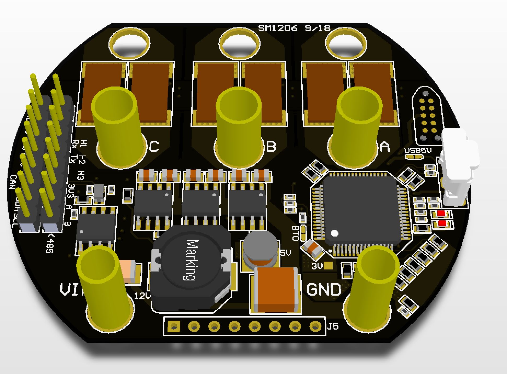
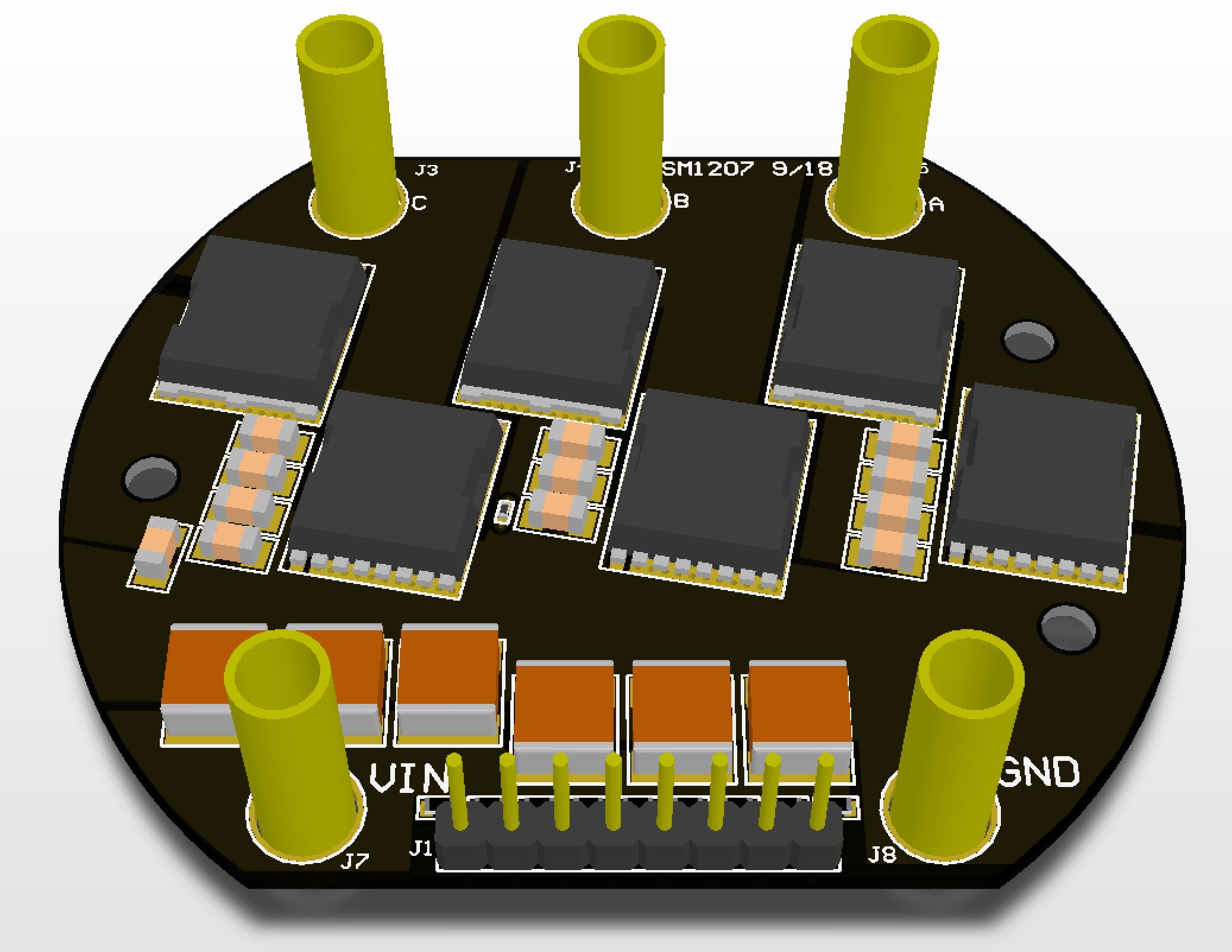
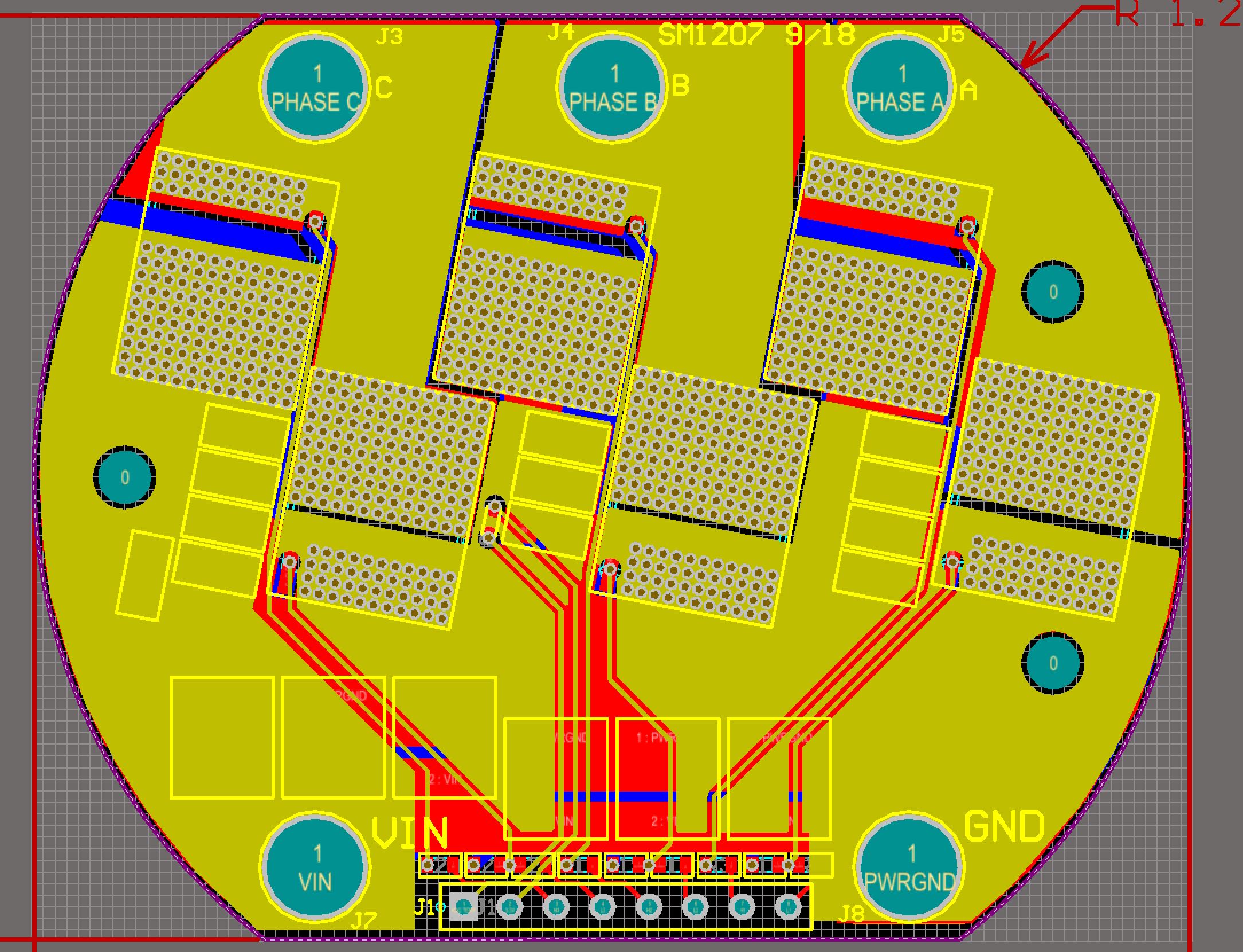
Max, I am working on that right now. Actually the electronics design is done except for sizing the gate resistors, and right at this moment I am deciding if I want to pay extra and wait longer to have the prototypes populated for me. The electrical schematics are VESC6.
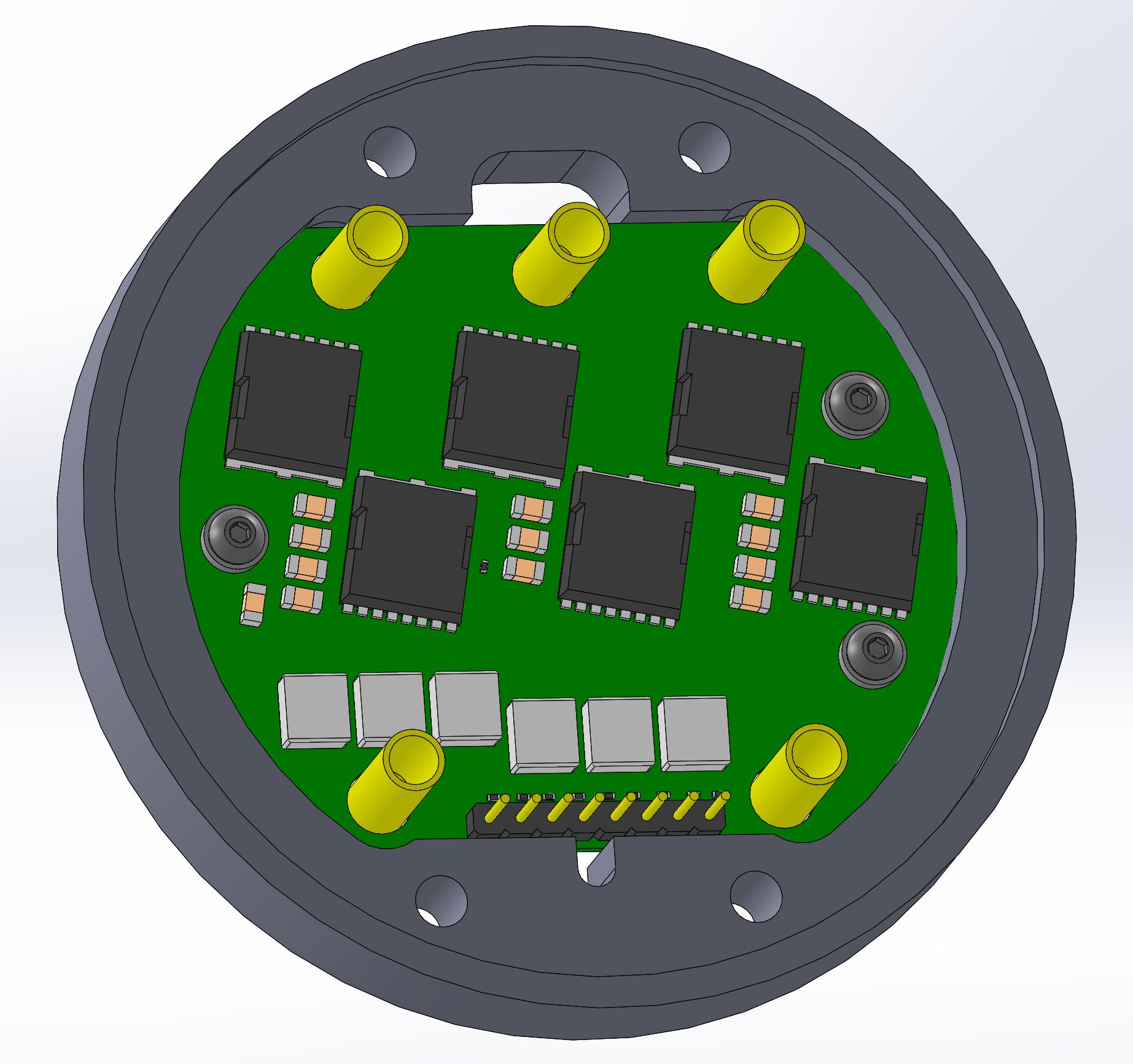
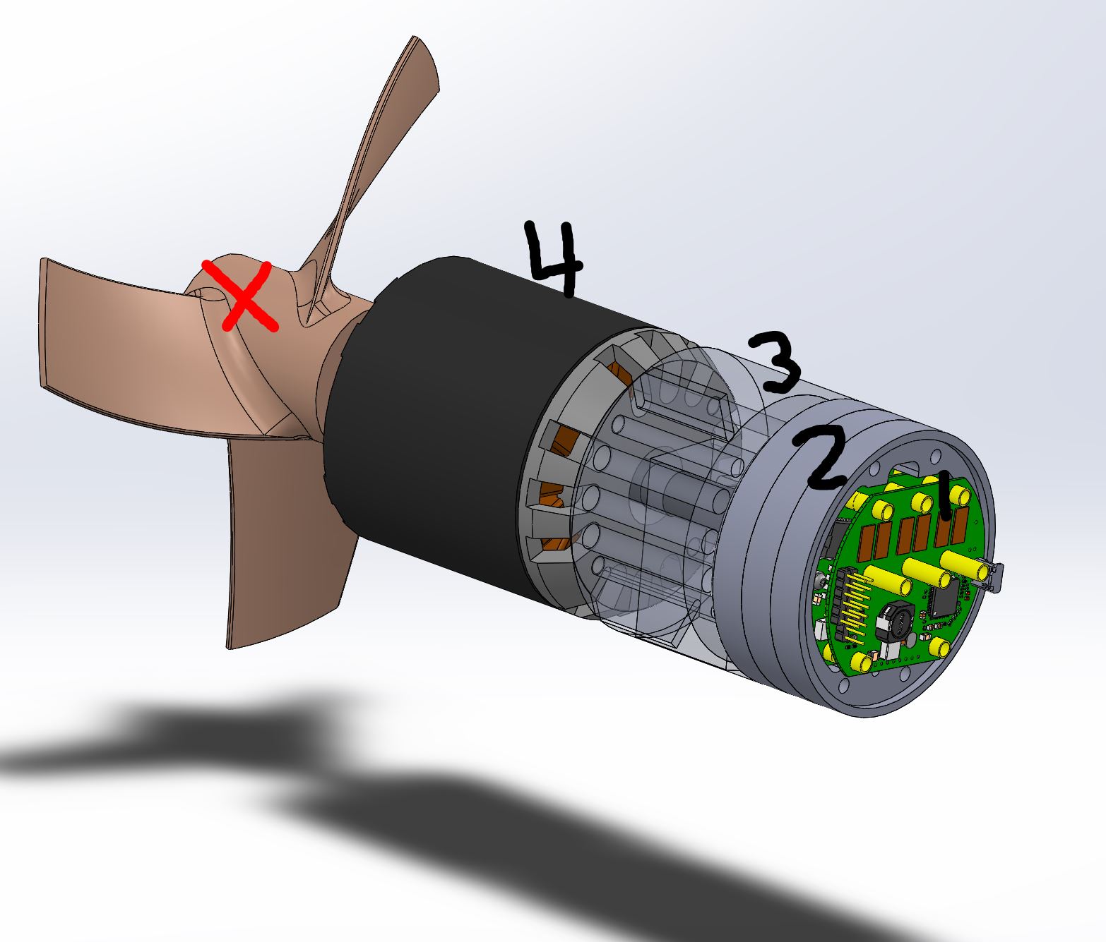
Here is my mechanical design concepts of how this fits together. I plan on making it over the next couple months. This design is a two board solution. There is one logic board and 1-4 stackable switching boards.
The switching boards are flat on the back and have screw holes so they can bolt into a cup-like thing that acts as a heat sink to the water outside the thruster.
The assemblage of electronics (1) and heat sinks (2) bolts to a motor adapter (3). The motor leads pass through the adapter and are potted into it, so the motor adapter and motor are permanently connected. The adapter is the seal for the back of the electronics, which can be air filled or oil filled for deep water. The adapter also holds the struts that connect the prop guard/kort nozzle, and it provides surfaces for thrust bearings to push and pull on.
The motor adapter is heavily dependent on the motor. Different motors will need different adapters. The motor shown is an APS C80100 130kv, 7kW motor.
Since the motor runs flooded, the stator will need to be treated with a thick coating of insulating varnish, and the rotor will need a 2 part epoxy based paint.
From back to front, the custom made mechanical parts will be:
Prop adapter
Motor Adapter
Heat sinks x3
Wiring housing/Connector mount
Nose cone/thruster mount
Mechanical design’s still in a rough state. I haven’t flashed out all the details, but I do have enough to be confident (in my own crazy head) that it is do-able. Once the prototype boards are ordered I’ll have some time to finish out the mechanical details so everyone can see how cool or terrible it looks.
It looks great again and like you have put a lot of tought into it.
If you have a seperate logic board, will you be able to use 2 Layer boards or is it just not worth the hassle?
It looks like it has most of the components on one side. If so I would opt only for the stencil and hot plate solder it. Only if you want to make many prototypes I would endure the additinal waiting for the assambly.
Elaborated Design! http://efoil.builders/uploads/default/original/2X/8/83244bfa1393dc97026b393869a0eb5702197fd1.jpeg
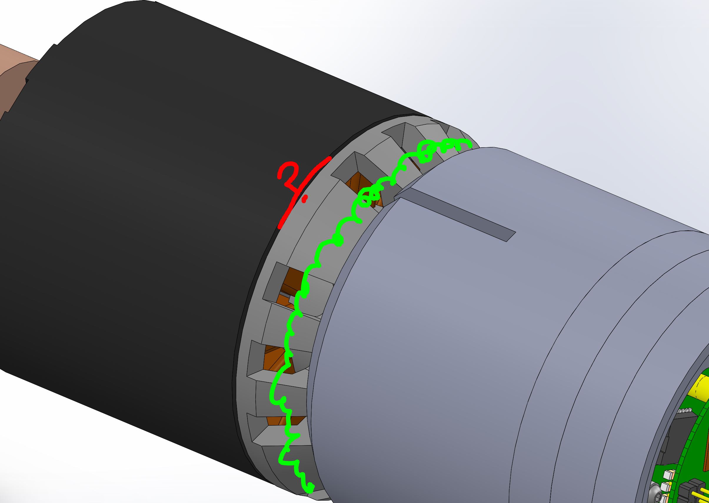
You should design a 90% cover of the all motor openings. This prevents sand inside the motor, so all openings which are standing still should be covered, so only the rotating have small openings. The water passes through the “mill”, the gap between rotor and hub, all heavy particles will be rejected to insert into the motor, only water is allowed.
So the only problem remaining is the circlip to not loose the rotor when braking.
@Flo The high power stuff is on the top and bottom layers. It would be cool to do a 2 layer aluminum substrate board, but this layout positioning isn’t super friendly for routing the gate drive wires.
@PowerGlider I’d love to cover the openings. I am going with a “flooded design” because a bunch of ROV/Navy dudes told me that oil-filled, shaft sealed designs are known to fail much more than flooded designs, even when the ROV operates in dirty environments. Perhaps I can put some reticulated filter foam around the stator openings. As long as the motor is spinning and the thruster is moving, the openings on the back of the rotor should be a low pressure zone, sucking clean water through the foam. But how do we put a filter on the crevice between the rotor and the stator?
@maxanderson I’ll be building and testing this board week after next I’ll get some video, and everyone can see if this design can meet their requirements. If it does, then we can put together a group buy to get whatever volume pricing we can get.
If people like the ESC design, it would also be good if we can get a group to agree on most-of-the-thruster design, so we can also save money on cnc Aluminum parts like ESC heat sinks, motor adapter, prop adapters, prop guards, etc.
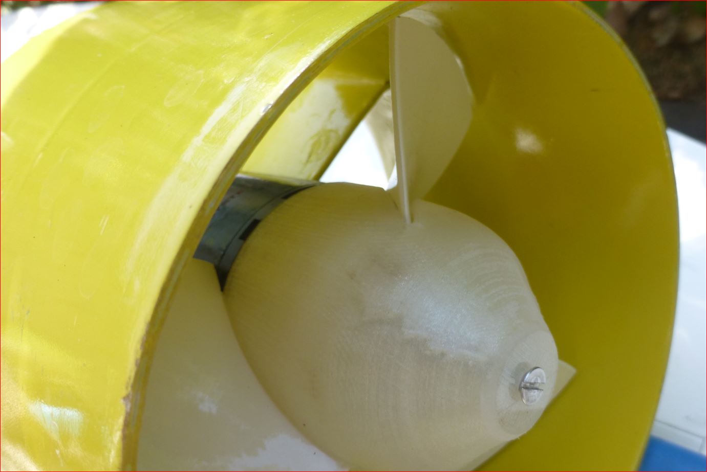
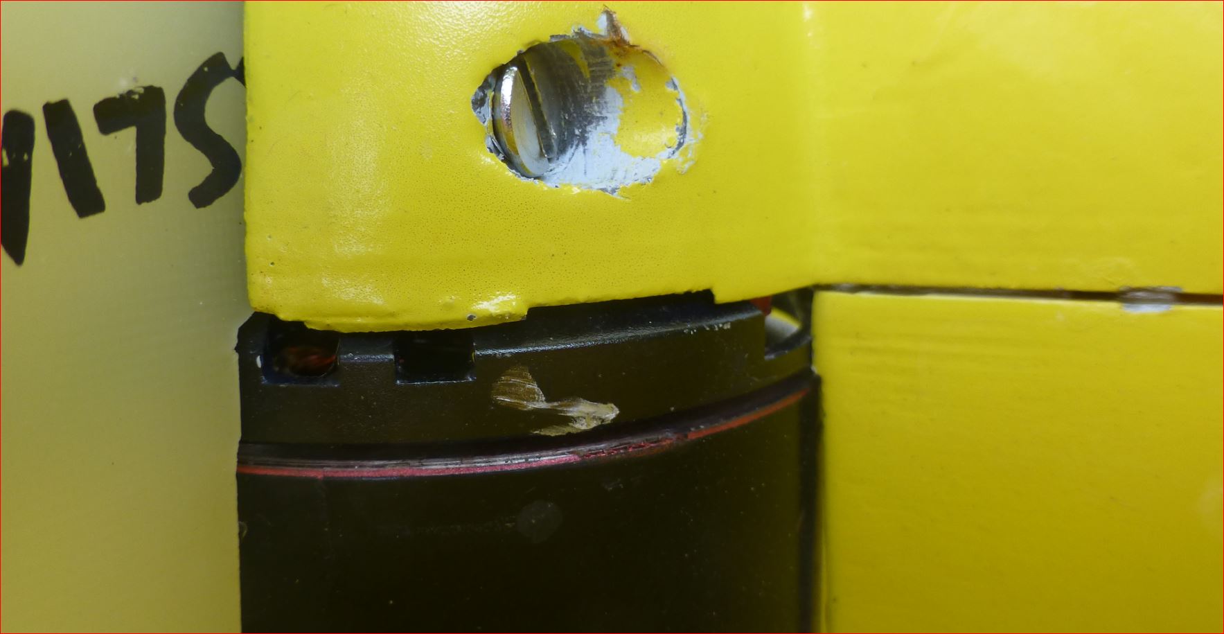
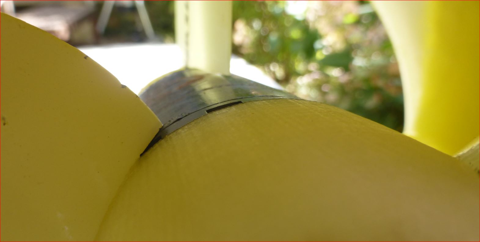
Right, you san seal at the green line and then you suck the water through the red marked slot only. It is not so dramatical. Here i have some details from my design, after it crashed into the beach at high speed, sucking pebbles and sand. Note the marks and scratches. It is still working perfectly, after reglueing the duct to the fin. This is not my end design, i want to experiment with different pitches and this construction is for eased swapping of heavily cut props, so the electric connection does not need to be removed to reach the circlip. I can swap the props without dismounting everything. The drawback is the not perfectly aligned 3D printed spinner.
It would be good to have a design which fits to 63mm outrunners as well.
If the cooling is good, one power board should be enough, 100A*50V is 5kW already, that should be enough for the 63mm outrunners. I also have plans to try 50mm diameter outrunners.
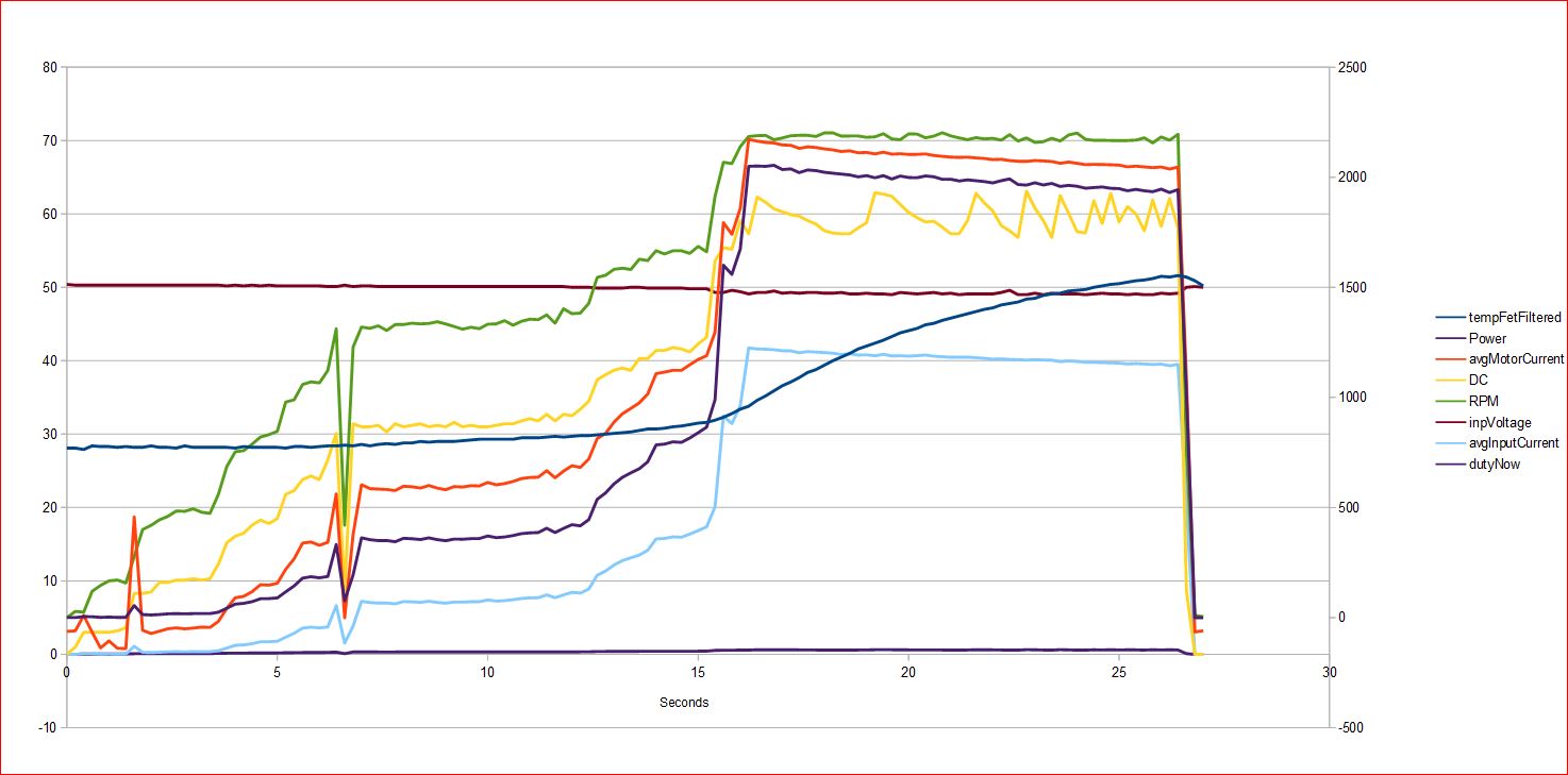
My VESC is really weak, the behaviour completely unclear to me, especially the DC, yellow.
I run the original FW with 0005 and phase current 90A. It is hitting fault code 4, FAULT_CODE_ABS_OVER_CURRENT
if i am correct.
Is this a fault in FW, because a single (and maybe wrong event captured anyhow) is repeatedly added into the FIR queue? Is the sampling timepoint correct or happening during a switching process? Is the filter time correctly chosen? How can it be, that the current is not controllable, what is causing this?
Then I used a leather belt wrapped around it to load it down when I want
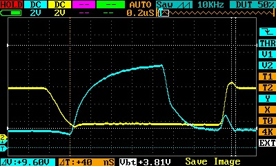
Used Vesc-tool and oscilloscope to capture sampled data.
Varied the Maximum Switching Frequency, Absolute max current, Slow ABS Current Limit FW values with Vesc-tool.
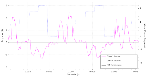
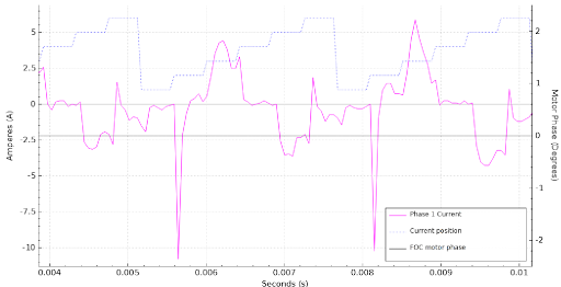
Here’s what I found: If you run at 40kHz sampling, you can see individual humps of current starting from zero, going high, and winding back at zero on each commutation step
Switching at 20kHz, you get half the resolution, and very strange spikes during commutation. Those are probably not real. They could be a digital artifact, but there are definitely big transients and second order oscillation on the o-scope during commutation so who knows. They don’t seem to matter.
Here is a comparison of the oscilloscope and the VESC data (red plot/phase 1):
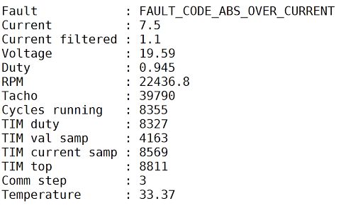
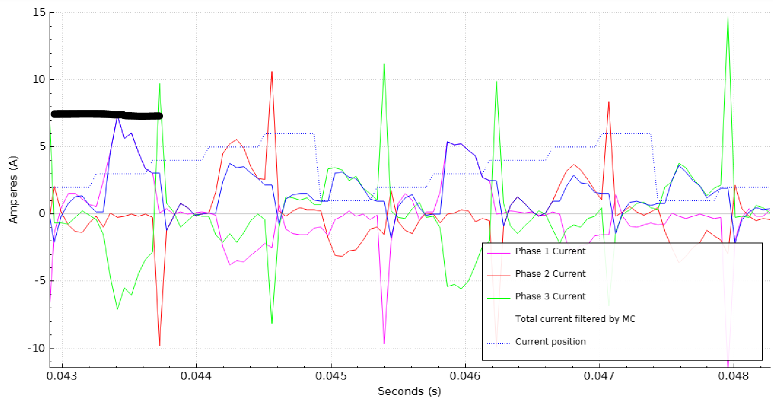
The commutation spikes don’t seem to affect anything. They happen at the ends of the commutation cycles, are way above the absolute overcurrent threshold, and I think the VESC ignores them. The peaks that happen in the middle of the commutation cycle cause errors. When I turned on the “slow abs current limit” feature, over-current errors happen less, but they still happen. Here is an error that I caused while sampling:
“Current filtered” is 1.1A at the same time the phase currents are touching 7.5A. Instantaneous phase currents are much higher than average motor current. This data is collected at low power, so there could be some noise and some small offset corrupting the data. With high power, I would guess the peak phase currents are around 3-4x the average currents. I haven’t done a sample capture yet with my new high power load setup.


