Would that be a problem you think? Maybe there is enough water. But a great way this whole 3d printing props. Totally new to me. For a few cents you can try all kinds of designs.
As a transfer function between throtle position and therefore between motor power and GPS speed, I was thinking that for a skate board it would have been linear. Due to water viscosity, we have some saturation levels here.
Is it possible for you to transpose Y and X ? Then we would see this:

Then we can see more easily IMHO where KW are not converted into kph. And the 40kph horizontal asymptotis or ceiling or horizontal saturation level where KW are poorly converted to speed…
It would also be interesting to trace the optimal curve through the cloud of points and derivate it to observe the max slope so the best efficiency areas where the minimlum increase of power produces the maximum increase of speed.
As a second survey, it would be interesting to compare the above curves to a static pontoon push curve using a bathroom scale, to get the
pressure (kg) as a function of (Average of power in KW or rpm)
As a third survey how does pitch influences the curve slope and where (in KW or rpm)
When understood, can we create the optimum prop with variable pitch able to offer the best speed to PW or rpm ratio ?
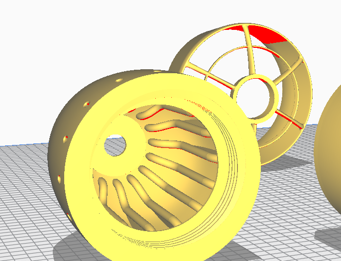
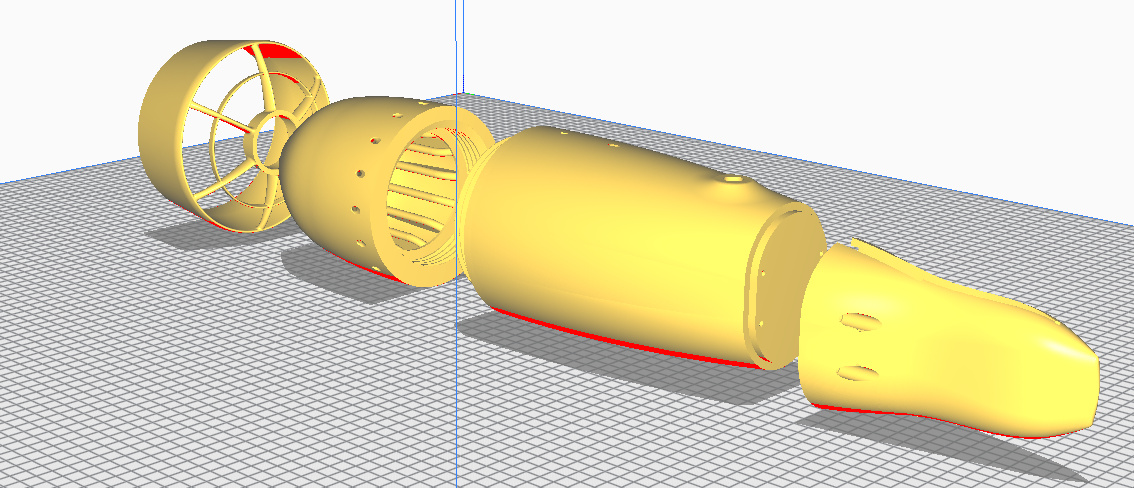
Can you make the shortest design possible?
Align the prop almost to the motor and shorten the complete construction to 50-70% length.
I think the blades are not twisted enough, but it is hard to tell from a photo.
They should at least grow linearly in thickness towards the hub in ratio to the radius.
Your build looks very powerful. Have you ever tried aluminium props? Are you afraid of being hurt? I can understand.
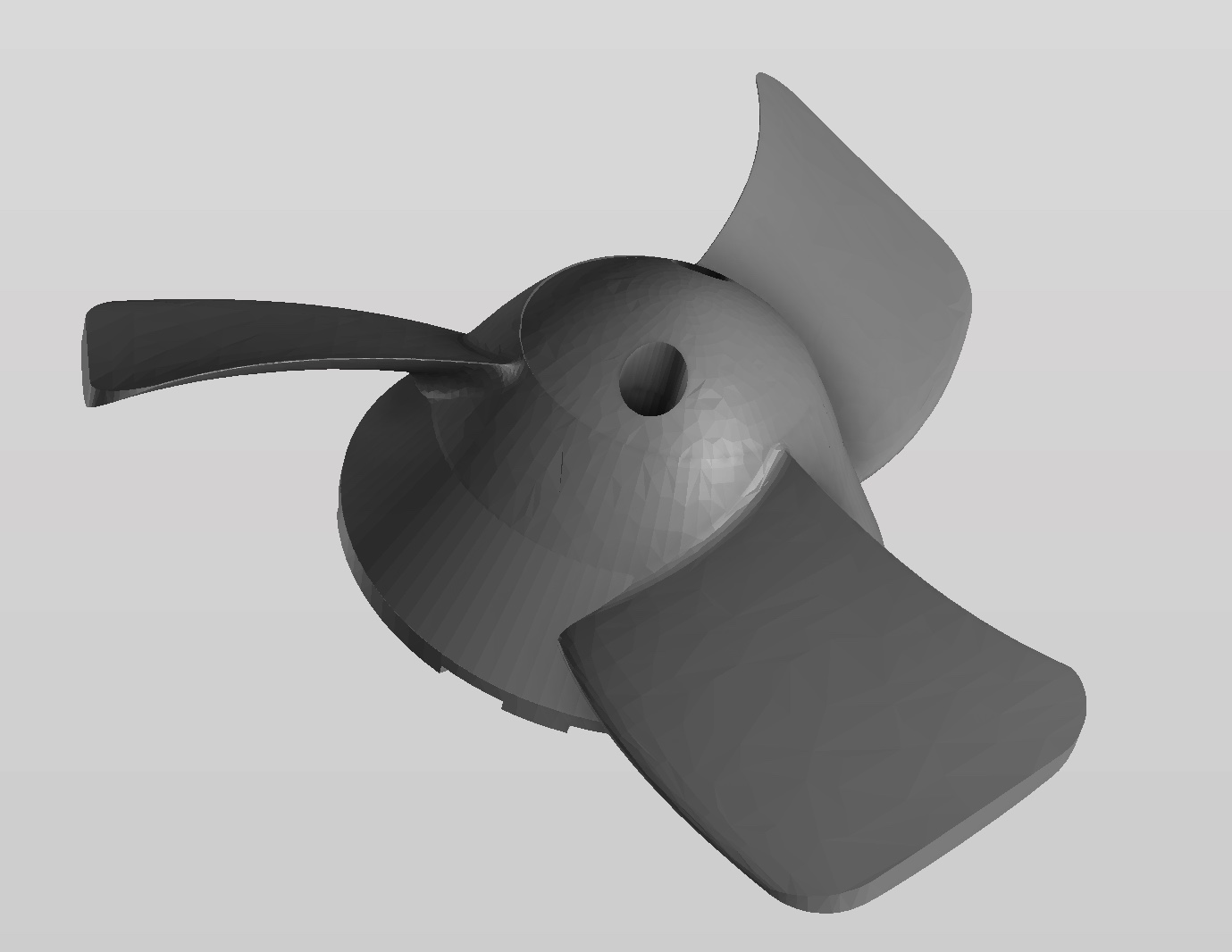
Maybe your V2 has to much surface, and making it a bit more stubby could be a solution.
Just a quick and dirty draft
1 Like
I think the 40kph ceiling is also probably due to the wing i’m using… the impulse wing is quite thick.
last time i wanted to try a thinner wing to see how it impacts the speed, but my cooling system didn’t want me to stay in the water…
Red and black were the same blade shapes. Red was with slightly less blade area, more rotating surface and i think more “flowy” flow 
I’m not sure of the exact parameters of that prop… i guess it’s measurable in the fusion file …
The black dot prop seams to work very well. The increase in power requirements between 10kmh to 25 is minimal. Looking at the graph it starts to fly close to 10 kmh ? After the speed of 25kmh probably the resistance of the foil starts to increase rapidly, thus the steep increase in power requirement. Possible also this type of propeller does not work that well in higher speeds but believe the main cause is the increased drag of the foil. The curve is not that far of a planning hull, at very low speed not that much resistance but before the hull planes properly, high power requirements and not that great speed. IMHO Bollard pull test results does not correlate much for foiling speeds if looking for prop design, totally different situation. Possible can give some info about capability of slow speed performance , speed before flying, but tells nothing about higher speed performance.
I think it sheds some light on hidden propulsion set details.:
1- you can test the prop power over the whole rpm range that is 0 to 4000 rpm without the interfering foil drag
2- you can locate (rpm) the propulsion set strongest “grunt”
Best of all, you can compare easily: on point 1 and 2 without leaving the shore:
3- different props, for example, why at 3KW is the the black prop 12% faster than the red prop - 28 vs 25kph,
4 - different motor specs with same prop,
5 - different ducts,
[Edit] new ideas since first post …(date yymmdd)
6- choose between 2 ESC timing settings (190613)
7- tbd
Did not mean to be harsh and fully agree testing sheds some light but to interpret the results from bollard pull to useful data for flying with a foil, is a challenge.
- Yes but the result is probably not applicable in the " real world" application, the achieved rpm might not be the same due to so different hydrodynamic conditions in a "static" situation. RPM and power requirement is depending on the load(heavy vs light rider) and
a bollard pull situation is not even close to foiling condition. The foil drag is a reality, and each propeller will react differently to each foil profile, do we really need the information given without the foil drag?
- Again Yes, but that will be the strongest grunt in bollard pull, no guarantee this is applicable when the propeller is working on a actually moving object.
For sure testing is worthwhile, especially for the electronics much safer to test how it can take the loads. But can You really predict real world performance in this type of application based on bollard pull is another story.
Let me give an example. For simplicity using an 5hp outboard engine (Petrol or electric) on a light foil boat. You do 3 different bollard pull test’s.
-
using the high pitch prop: 7.5 X 9
-
using the high thrust prop: 8.4 X 6
-
using the high thrust prop: 8.4 X 6 but adding a rice profile nozzle around the propeller.
No doubt the best bollard pull result will be option 3 and the worst for option 1. Rpm I dont know, pending on cavitation, but will probably be different in each option. So now we have hypothetical test result.
For a slow going heavy sailing boat, option 3 will be best. For a light foiling boat, option 1 will be best, this for foiling speeds. To get the boat up on the foil, option 2 or 3 might be better but thereafter the 9 pitch prop works better.
So for lighter boats/boards a better bollard pull result might predict a worse actual performance, however this is not always the case, can be the other way around also…Just saying using bollard pull results for propeller optimizing to predict real world performance on light relative fast boats is a huge challenge. There is a reason why its called "black magic of propellers …
Thanks for your answer with use cases. I do not pretend to be a guru or to reinvent the wheel just trying to propose ideas, explore new paths (eg best motor timing) and more generally speaking how to make the best possible choice between a list of alternatives… confirm or refute a hypothesis within less than 5 minutes.
As electric foiling is a new subject, I would love to see this list of bollard pull pros and cons being enriched every day (new post ?). Lets imagine that, like a gearbox on a gas car we could highlight that EsC timing could vary with motor rpm … and ask the manufacturers to add a new feature called “Adaptative ESC timing”… just an example 
Me no guru either but i do have practical experience of boats and related engines/propellers in range from 1-300 hp and still learning more every year. On one of my boats tested 7 different propellers, none of the results was logical compared to theory and specification on paper, you just have to test them in real condition to see how they work. Anyway it is always a compromise, are You looking for high top speed, torque or what. I am sure that certain aspect of the build can be tested stationary in a pool and have been thinking how to improve the result in bollard pull. One way (as also discussed here) would be to do it in streaming water, but again, then You will have less resistance for the propeller than in the real world so really don’t know what would be the right solution/ how to simulate with good correlation to actual condition.
My own idea of making life simple, if talking about propeller propulsion, would be to mimic torque and rpm of outboards and use their propeller, can not go much wrong. So many outboard manufacturers has been developing those for decades that think the design of those propellers must be relative good. The nozzle around propeller for safety reasons makes things more complicated but probably slightly cutting the tips would probably still work fairly good with a nozzle also.
Testing a set of efoil propellers with all the comfort of a sitting position in a small boat (the @Louis way) would be a nice test bench ![]() . Then there is this alternative, the surfboard fin (diY version to create) to install on a large and stable sup board… OK, there wouldn’t be the flying aspect but we would have the dynamic one the bollard pull does not offer…
. Then there is this alternative, the surfboard fin (diY version to create) to install on a large and stable sup board… OK, there wouldn’t be the flying aspect but we would have the dynamic one the bollard pull does not offer…
Many people including Mat have been testing the 12usd Solas plastic and alu prop with great success.
Who’s going to make the first benchmark test (Gps speed vs Power) from a outboard between a Flying rodeo 125mm and a shortened solas prop ? ![]() or from a boat fitted with the Flying Rodeo mast and pod .
or from a boat fitted with the Flying Rodeo mast and pod .
Hi guys
I discovered this forum recently.
I had in mind more than 2 years ago to do my efoil, I designed my stuff, first one based on an alien motor,
By discovering your smart approach to directly use apm engine with direct coolling, simplify th design to its minimum
Is there any chance to have a post with more details about the technic to isolate the motor, I read all your posts but it’s still not clear to me… I have esc flyers, alien engine same, I Baugh an alibaba baba prop, and 4batts 8s 5000mAmp/each +ender for 3d printing
Thks for feedback
Mat, where are U located?
Ben
Welcome to the adventure!
For the motor preparation:
Check out the doc written by @Vicdes2
https://docs.google.com/document/d/1UosI2KZN9h9E4q1G0ikiLPxTUhX5FFuk09xoBxRoY_0/edit
it’s more details, and you can also have a look at my video : https://vimeo.com/291837634
regarding the battery, you’ll do 8s / 20Ah or 16s 10Ah ?
What Kv is your motor?
and… i’m in houston for a month or 2, and then probably abu dhabi…
1 Like
Watched the movie twice. Incredibe! 
You also tried ceramic bearings? So many posts. I forget what you did and what you did not. The mounting 3d printing files are updated? Or can I use just the one in this topic?
Thanks
I didn’t tried ceramic bearings… lead time to procure them was too long, and the open / stainless steel ones i have are doing great, i let the salt water in the pod for a week before opening it last time i went in and they’re brand new… only problem is the magnets that i can’t stop from rusting i need to look at them more seriously
If you go from the end of the topic up, you should find my latest 3d files… there were some improvements between the beginning and the end double check that the pod will fit your mast (mine is a recent Liquid force)
Still using the corrosion x after a few runs ?The 2k epoxy spray in a can was not good enough to cover the magnets? Maybe some epoxy? If it is too tick maybe it will scratch off by letting the motor rotate? I will look up your files, thank you. I have a F-one foil mast. I think I will give your 3d files and my mast to a friend so he can draw a new file. Ill share that in a new topic if it worked.
yes, regular corrosion X and i’m usually flushing the pod with fresh water… but i forgot the fresh water home last time…
I didn’t got around to try the 2k, it was just suggested to me… may be this time
Hi Guys,
Thks mat for your feedback.
I will try to quickly summarize my project. Started in summer 2017 before my second kids. Then time to time on the subject without huge motivation. Difficult Kids…sick…
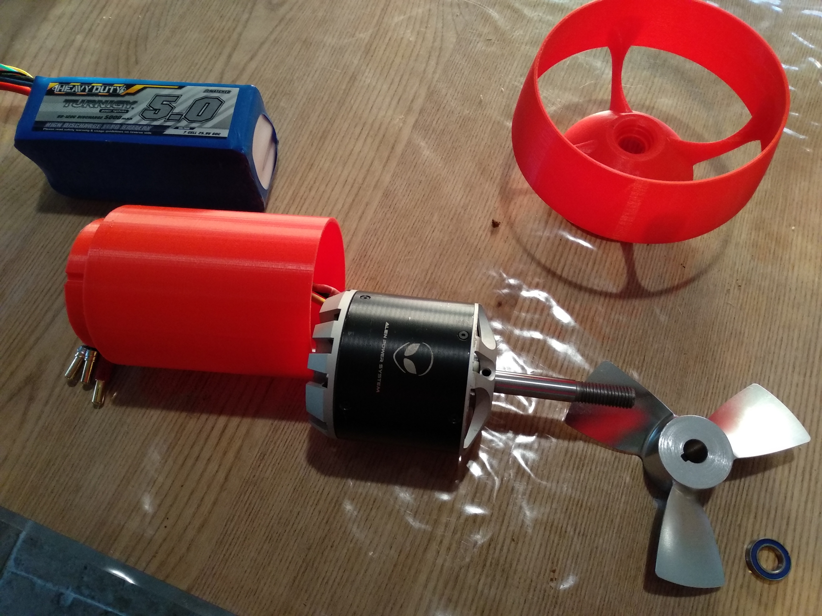
My initial design targeted the use of APM alien engine. 6000Watt. Exactly : C8085 Outrunner brushless motor 170KV 6000W / xas Available in august 2017.
According to base designe d& personnal analyze : Low speed for engine and “Good” torque was the Key.
A 300A ESC boat module ; water cooling.
Key concern was the Cooling process for Engine & Controller. First idea was to create large container with lot of space and contact to cool Down the motor with cavity for water to go through.
With ESC Controller behind Engine with direct water Entry.
BMS charger is a Max 8S module with plenty options… A very nice stuff… I had some issue to identify a product able to charge more than 6S lipo. Up to 6 it is quite easy and upper quite boring to identify.
Battery is a 7S 5000MAmp from Turnigy 60C / 4 packs of this : 2 in series mounted in parallel to reach 14S /20000MAmp. Almost 4,5Grams of L
Propeller is something difficulty bought in Alibaba at this time / Quite a nightmare to find a propeller with for me appropriate characteristics of size, Shaft constraints & good Pitch.
After a while a couple of printed object I reviewd my “Container to something smaller and less complex.” / If with 3D printer it is quite easy to print / Making an aluminum structure is quite impossible.
==> See Internal “tube” to cool down internal cavity of Engine.
In terms of Static test : battery / esc , motor and prop out of Water ; it is quite Heavy in terms of ACTION… Propulsion. Quite dangerous to get this rotating stuff not far from me… I will try to share this Video once found back…
Now my second approach was to reduce container to strict minimum / Thinking “Now” that Heating won’t be too problematic / Which now seems finally the KEY problem. Or at least one the the Key issue. Right now my container is much smaller, just enough space to mount engine inside.
I loaded some picture to illustrate this.
But as beginners / Only 1 image… See Next Post…
Finally, NOW my plan is to move forward for my efoil this year; So back on line and checking news on it ; I found DIY video from Martin ; In fact I found it 2 year ago the first one and then I did not follow it anymore.
So by going deeper on the subject ; I understand that for smaller eFOIL tube you need to reduce the engine and it goes through a Reductor. I Thought about it long time ago but I could not imagine something doing this job with such rpm and torque and this “thin” size. I got Wrong for this approach.
Anyway, I may have now to conclude about what to DO , either I continue with all my gears available changing my approach to "Mat’s one ; Also in parallel try to start as PacificMesiter!
Let See
First I will check the way to isolate my motor. I will revert back to you. I have plenty questions on this method and also bearings…
benjamin.R