Hope you get results on this soon! Would be interesting to know if it really makes a difference. I had the same debate with eskateboards. Never came to a conclusion on that. Way safer to have the prop where you have it designed.
I asked around regarding efficiency and got an answer from the guys who make this: http://candelaspeedboat.com. They looked at both and found no real differences for their application. To gain on efficiency, go duoprop.
Whit that said, the only way to know is to test. I’m thinking it might have an impact on the ride since the pulling force is located in front of the mast.
Anyways, I will make one board with two masts that fit the same foil. This way I can change in between them.
Br
Rikard
If you are using an inrunner, no need to cool it from the inside since there is only the magnet and that is not the part that gets really hot.
The only think that needs to be cooled down is the stator and in an inrunner it’s located on the outer diameter .
But where did you find a 100Kv inrunner ?
This one ?
Hi!
First off, this is trial with high stakes
The plan here is to cool everything as much as possible, hence the hollow shaft.
I will be using parts of that motor as base.
BR
Rikard
Thats a cool way of things!
Looking forward to seeing it succeed, keep us posted!
@Riwi Forward facing was the best solution Volvo came up with using HUGE R&D funding .
See:

I am also looking in to this : Contra Rotating Propeller - #2 by Ralf - Propulsion System (Motor, Gears) - FOIL.zone
Very keen to see your progress !
That’s forward facing duoprop. Duoprop is the big gain here.
Update!
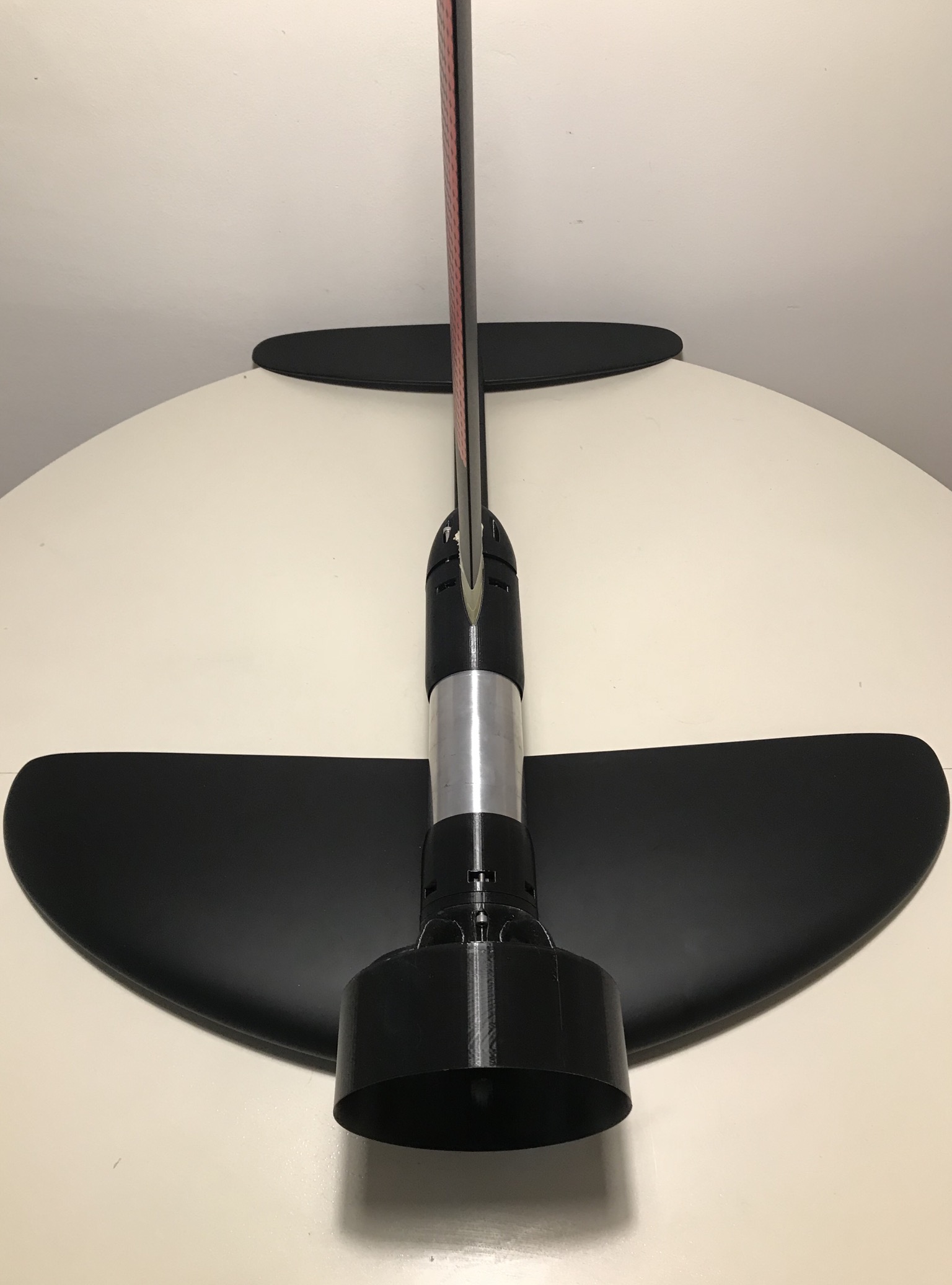
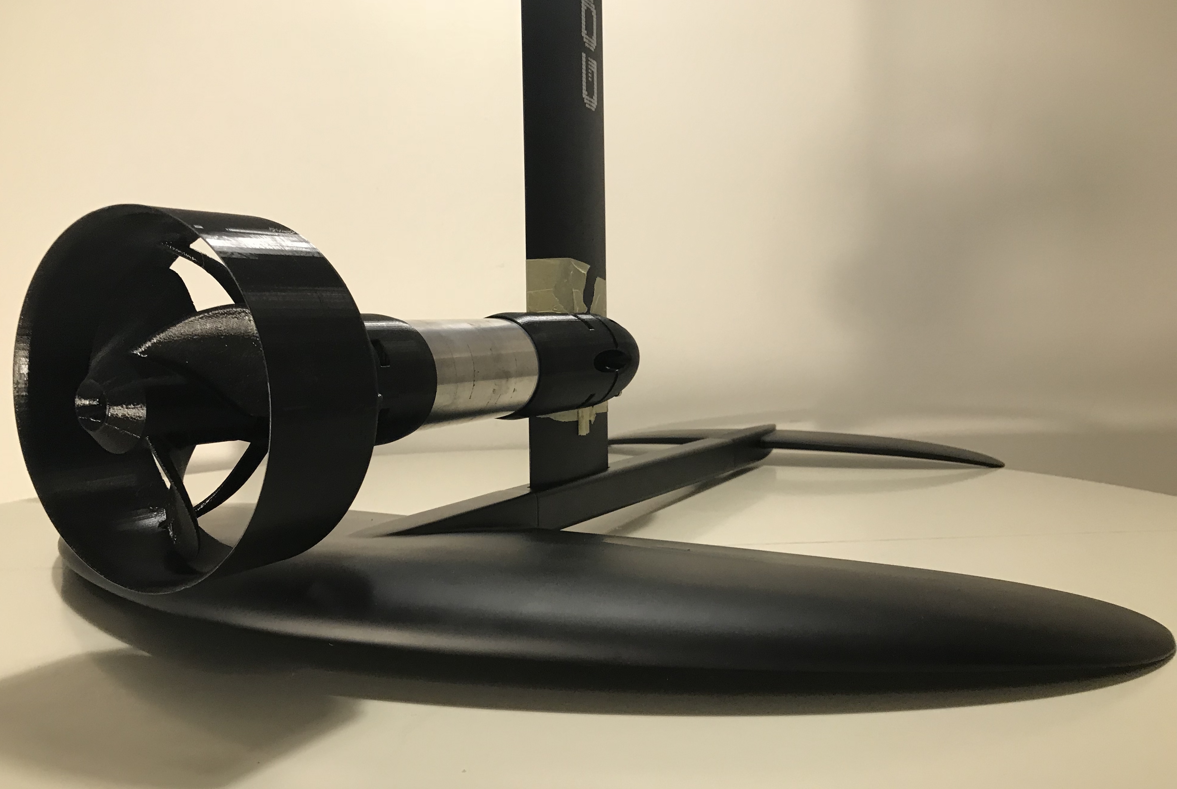
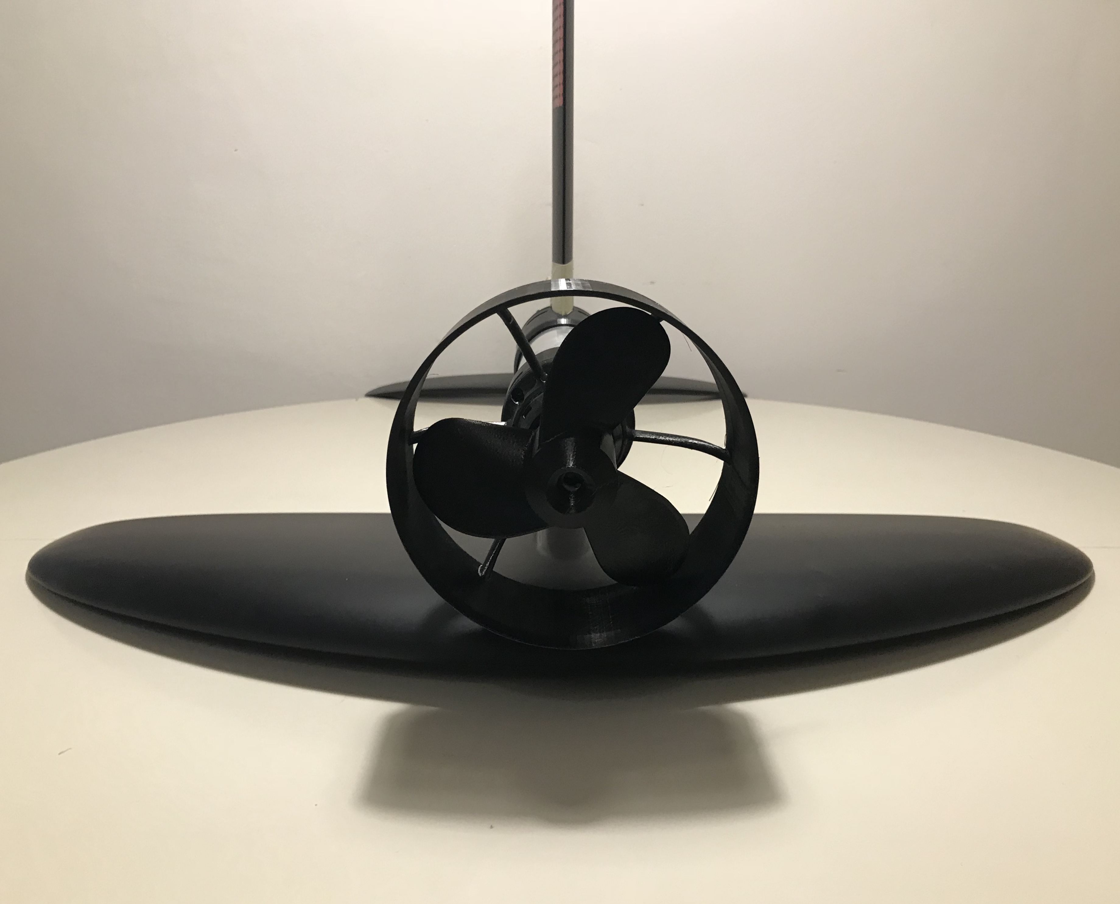
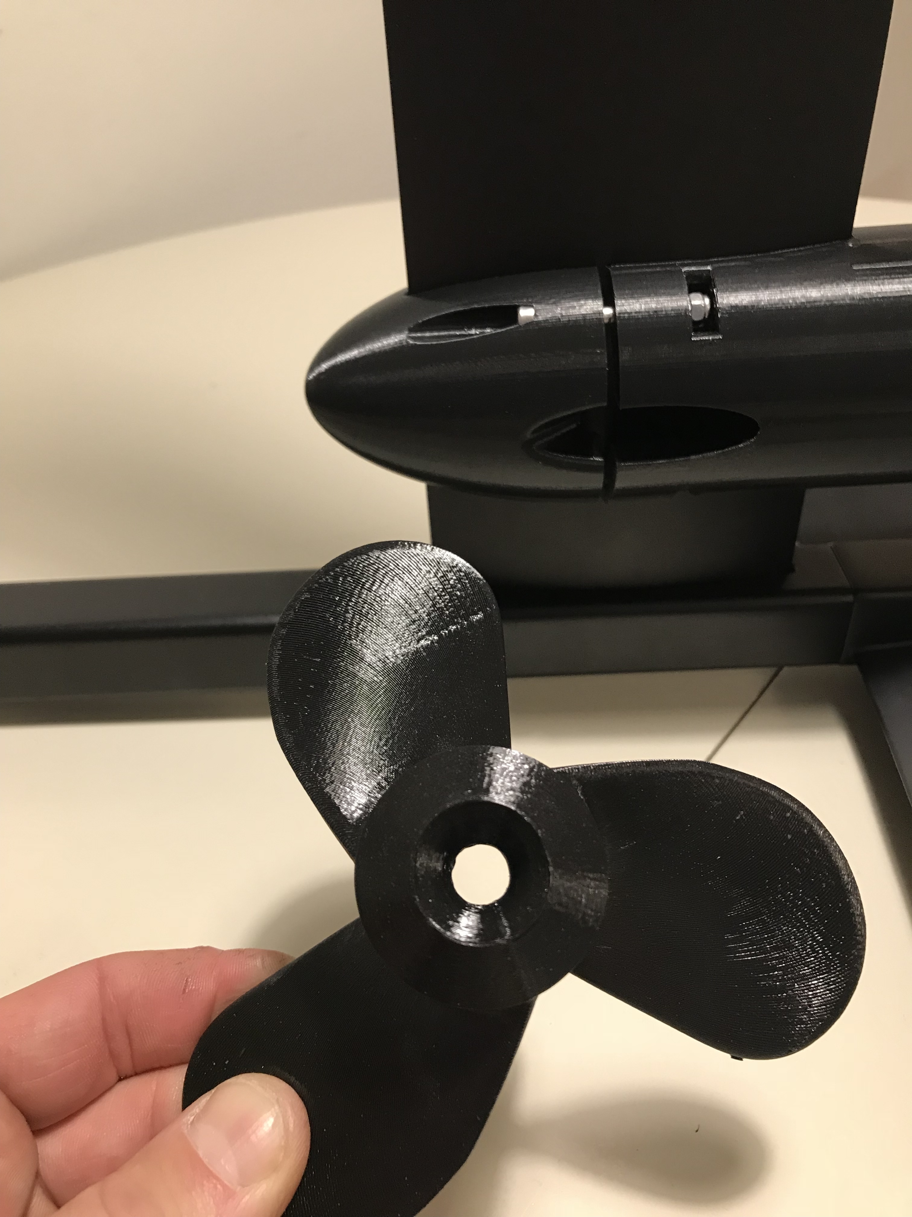
Got the parts from the printer today. Looks good.
I also managed to get a hold of a stainless tube 10x2mm that will act as shaft.
Waiting for rotor and housing from Alien.
4 Likes
Water is forced into the center of the prop and trough the hollow drive shaft. There is an opening on the side of the mast mount which lets the water escape after cooling the motor from the inside.
Standard aluminum tube is used to conduct heat from the motor housing.
I’m going to try and heat the tube so that it expands before mounting the motor. I will add one extra layer of alu tape to the motor and have the aluminum tube squeeze the motor in place when cooling.

2 Likes
Cool, do you have a photo of your hollow shaft? What is the inner diameter? Maybe, it could be use for dual prop setup
Thanks
Stainless steel, 10x2mm.
1 Like
you don’t put the thrust bearing on the back of the motor near the mast?
sorry but i don’t see how the pulling force can be applying on the rear of the mast by the shaft?
what is your idea to hold the propeller and the rotor on the hold shaft, pin? weld?
Look at the first picture. I replace the original shaft with a hollow one. Thrust bearing is placed inside of the ball bearing. Prop is held onto the shaft using a ensat thread that is machined to fit the hollow shaft. More pictures coming as I get the motor.
yes i saw the first picture, i was wondering why you chosse to put the thrust bearing at the place, pulling force on the mast will go by 3 parts (glued?) instead of just one at the back ?
I agree with @Alexandre having the force placed closer to the mast would be an advantage as the forces will not be pulling the two outer seals apart. moving the forces towards the mast helps to remove a mode of failure.
@Riwi you are doing some very clever stuff it is very nice to see the creative thinking & design work that you are doing. I look forward to seeing the development.
Best regards,
Alex (AKA theone)
Hi!
Ok I get it! That’s great feedback. The reason for placing it there is to make it serviceable. Since the alu-tube will be glued to the mast mount I won’t be able to reach the bearing if it is placed behind the motor.
It might be that the epoxy or the 3D parts won’t be powerful enough for the thrust. We will see.
I guess the mast mount can be redesigned to house both the shaft seals, the shaft collar and the thrust bearing. A great idea for version two 
Thanks
Rikard
Using a stainless thrust bearing and a stainless shaft collar would make it possible to have them on the “outside”.
The duct would be redesigned to house both seals and the ball bearing. The part in between would be eliminated. The duct would be fitted to the 3D part that is glued to the tube…
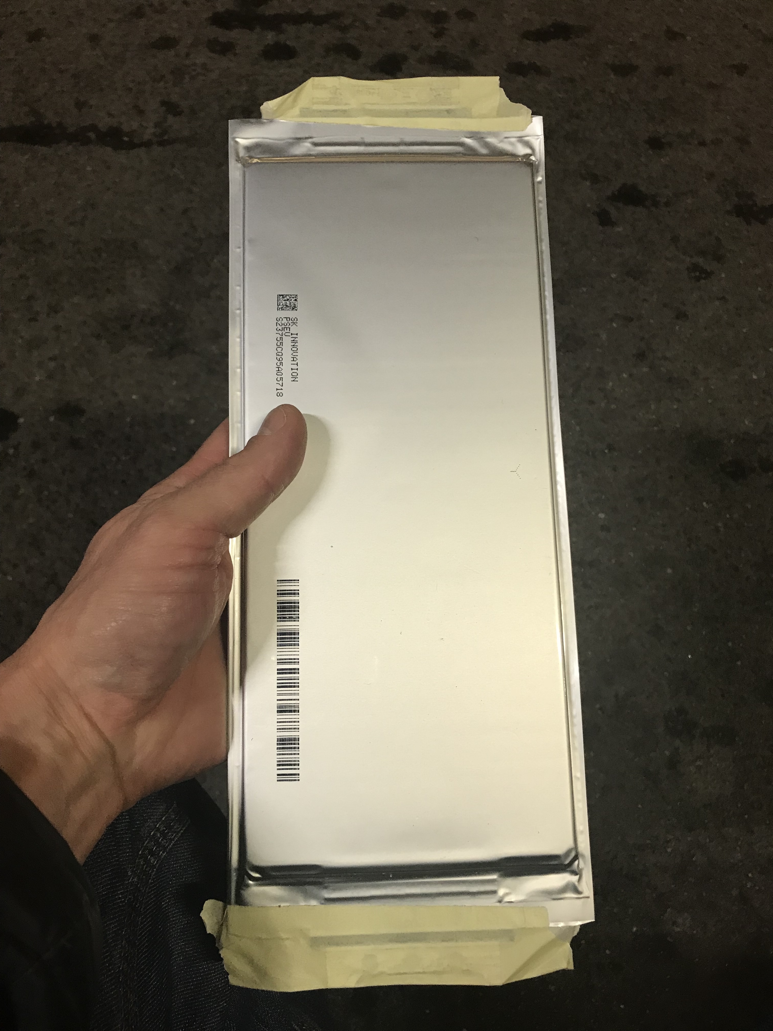
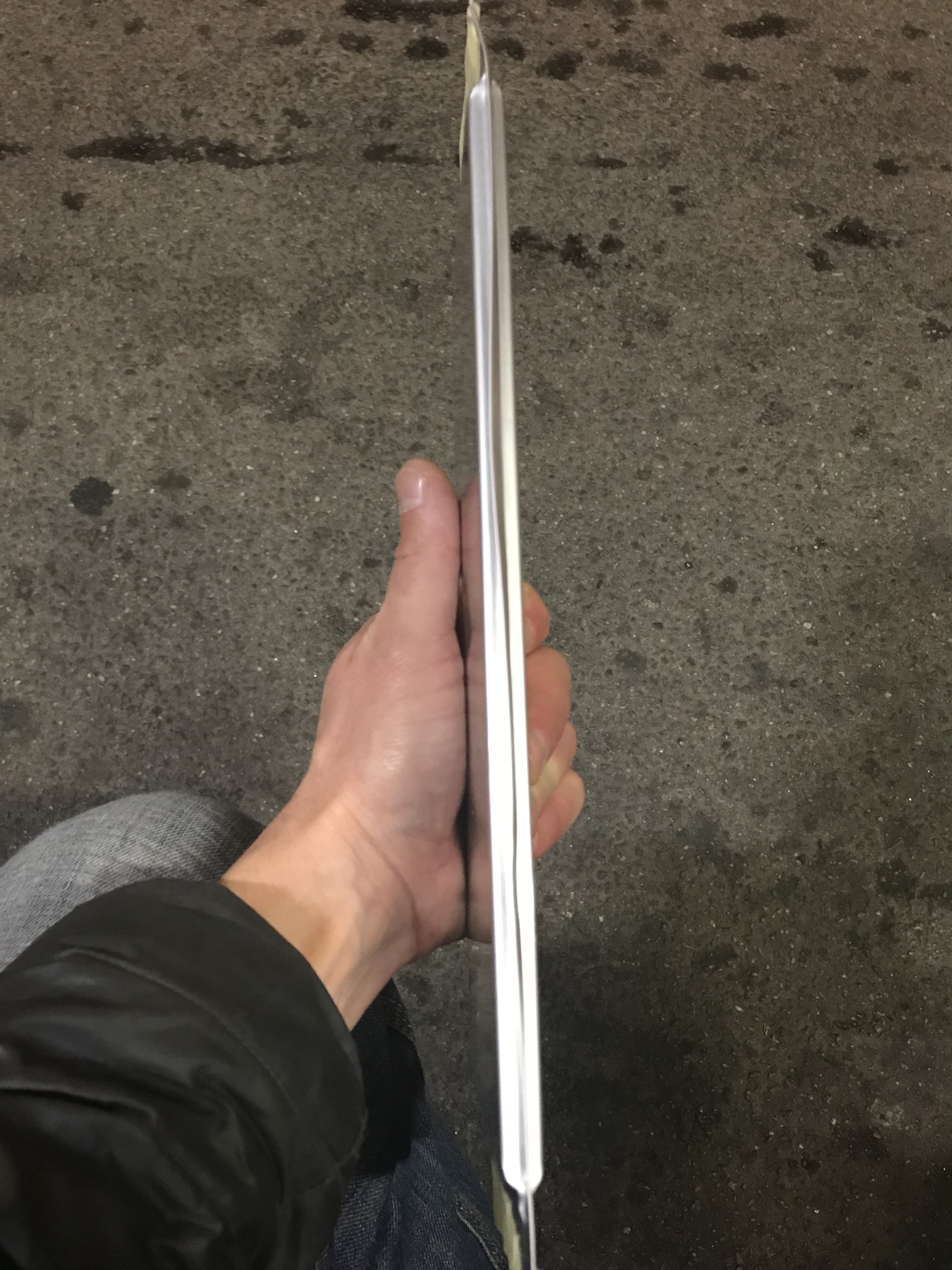
Let’s talk batteries. I know cylindrical is the way to go but I like it simple 
Just got my hands on 12 li-ion cells from a banged up Kia Soul. Cells are 42,5ah 4.2V and the weight is 750grams. They can handle 10C without generating to much heat.
I will arrange them in two 6s packs.
2 Likes
Shared. I am tempted to add that this pull setup is not present in the 6 patents I’ve read so hopefully cannot be patented now.
2 Likes
Haha! I love that fact
Foil to the people!!!
1 Like