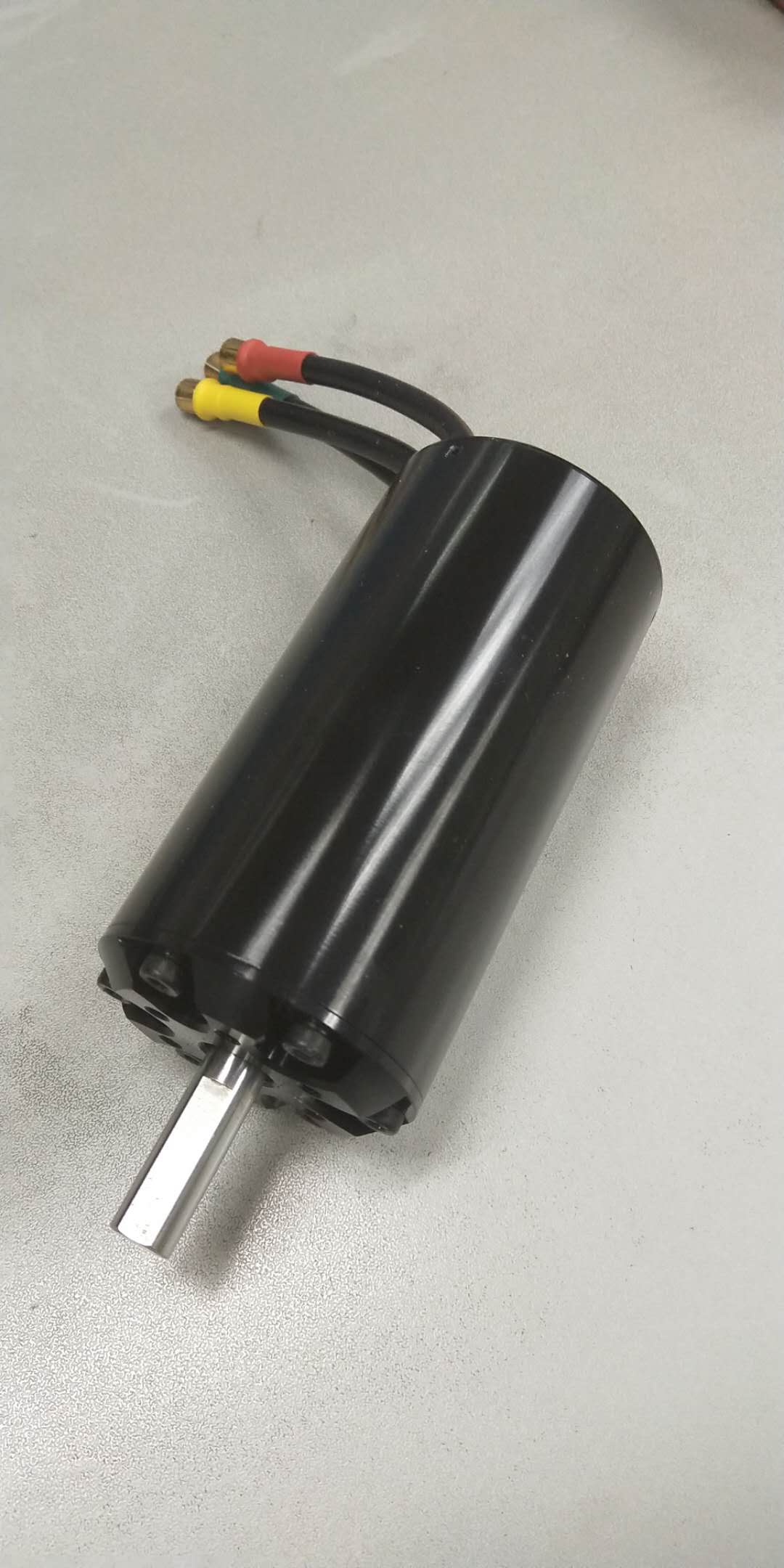
It makes no sound. If it is an outrunner, I guess it is cooled only through the mounting plate.
If it’s the case, it opens a all new era for us efoil builders !
It means it’s possible to contain the heat and make custom housing with outrunners mounted direct drive without any cooling.
1 Like
So I hooked it up for the first time today, there are a few things that I have noticed…
- the magnetic field is coming through the stainless case ie. I can stick metal objects onto the case.
- The current draw at 50V was 2.2A. Therefore 110W.
I have 2 identical foil setups so it will be really interesting to see how differently they perform with only the motor and prop being different.
1 Like
Mount the propeller you have, hold all together into into the water and start with low RPM and power. Monitor the temperature by frequently stopping the process, take it out of the water, dry with towel, store in dry towel, measure the surface temperature at different places after some time, estimate the inner temperatures after a given load profile.
1 Like
C’mon Max! Wet that board, summer runs fast up north, I’m super curious to know how it run that direct outrunner sealed, I’m thinking the possible 2.0 for next winter!
1 Like
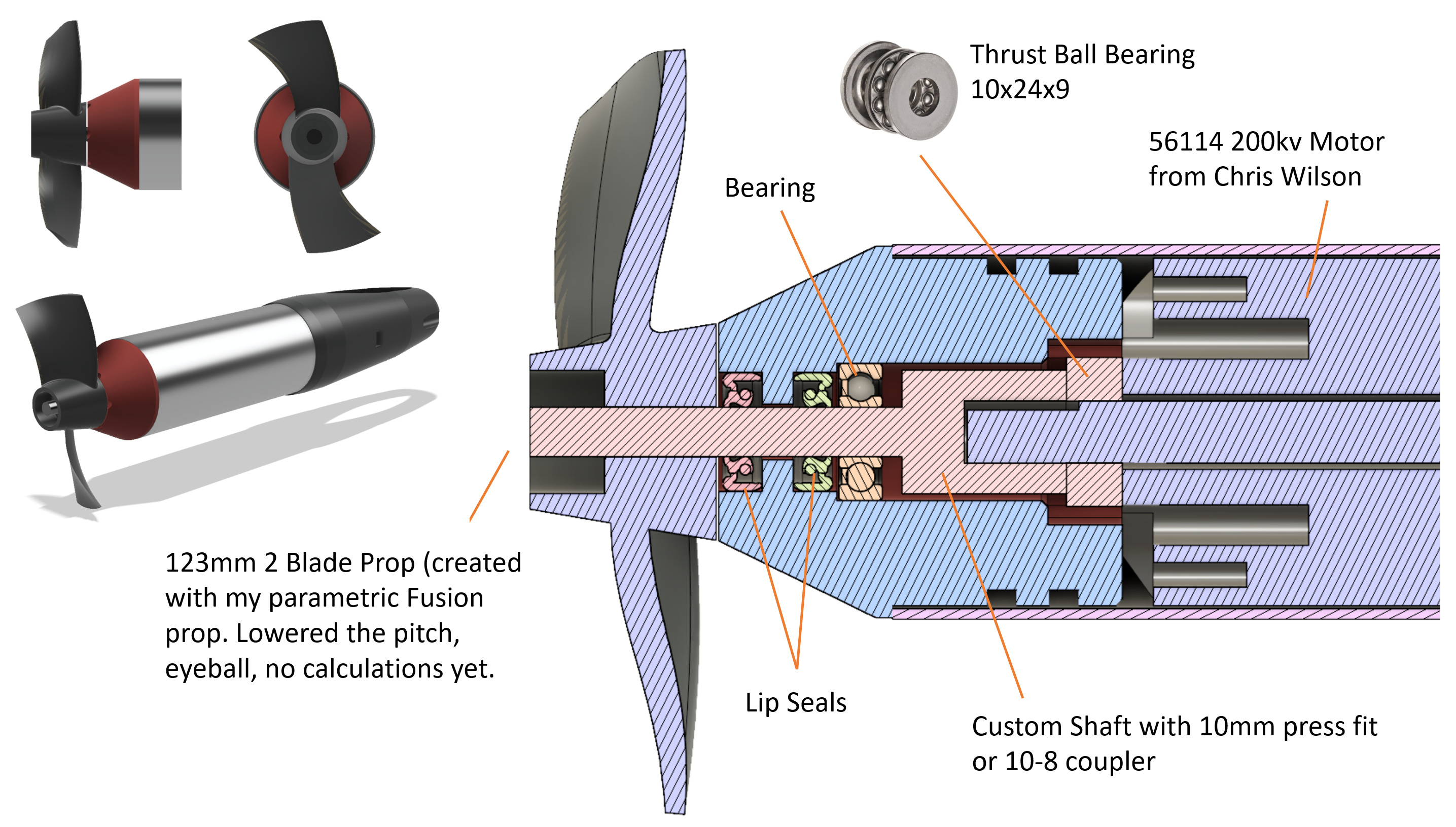
ive made a 56114 200 kv motor to try direct drive it was sent to pacific to test out my hope is to come up with a turn key motor for our use. so any suggestion
.
2 Likes
Slow progress on my side with this, sorry. Right now I am thinking about trying an open 2 blade prop with slightly lower pitch. Here is what I am about to build. Thoughts welcome.
3 Likes
Any thoughts about the importance of the tail cone? My motor has a diameter of 70mm, so I am not sure if it makes sense to start the blades at 40mm diamter or go to 70mm straight away.
I have been wondering it too Max. I donn’t think it matters a lot. The speed is much higher on the outer part of the propeller than on the inner (more speed comes with biger diameter).
Also, after looking at many propellers mounted on outboard gaz engine, there is no cone.
Actually, there is the opposite of a cone, something to forward the water flow away from the axis of the propeller.
I’m planning on trying both to confirm my initial thoughts
1 Like
Why do you use an additional outer aluminium pipe? What is the purpose?
Why do you need a thrust bearing?
Why do you need a coupler?
Why is the drive shaft of the motor so short? It should have a hole instead of the planned area.
Cant the lip seals be integrated into the motor mount?
I agree. That’s why outrunners are so much better. Direct drive…not couplers, thrust bearings, extra shafts or gear boxes. I think you can get rid of a lot of those parts. Running 7k RPM …you will need a pretty stiff prop.
Yes a longer shaft wit built in seal etc can all be made, fo the moment we just need to confirm the KV and prop then i will integrate everything into the housing.
1 Like
Hmmm, That looks suspiciously like my build? My 360kv SSS might spin the 80mm 1p prop off aliexpress ok.
Might get 20kg of thrust which might be enough to float on the SUP wing.
I have the same 10x24x9 thrust bearing. It fits so well to the SSS motor. Im not sure if I can get the trust from the shaft, through the coupler to the trust bearing. That custom shaft looks better.
Im going to run the housing with a fine tolerance to the thrust bearing in the hopes that I can get lubrication to stay in the thrust bearing. Also im attaching the motor to the housing (blue part in yours) and the attaching the housing to the outer tube behind the two gaskets.
I might try and steal your prop if the 80mm doesnt work on mine.
1 Like
@MaxMaker: for a waterproof electrical box, I did not try it but heard that chloroform sticks plexiglass to plexiglass seamlessly and beautifully. The joint returns to transparent (comparatively Cyanoacrylate result is shocking - eg SuperGlue thing) Chloroform might be difficult or impossible to buy depending on local regulations. It’s what was used for general anesthesia in hospitals until the mid 70’s with a jet pilot sort of mask.
“Acrifix” glue works like a dream on plexi.
I have used it, too. Even does a decend bond on PLA, I used Acrifix from Evonik. But it stinks nasty and the MSDS is not too short.
I have Acrifix. Good stuff, but I am bonding Perspex (Plexiglas) to PP. Thats sorted now anyway.
The VESC is finally working!!! So happy about it. Trampa send me a replacement and finally it worked, but somehow it still keeps powering my Arduino over signal and GND. I don´t care about it, I just make sure the UBEC is always turned on. I wasted enough time with this already. Two months just for the ESC.
Thank you to FLO, MaB, Tedd Orr from Trampa, Danny from DieBee Engineering and everyone else here that helped me troubleshoot.
Next up is getting my Settings to max out at 120A and then I can water test.
I guess I need to upload the VESC_default_no_hw_limits.bin firmware? Tips are appreciated.
And do I need to configure the VESC internal Temp cutoff?
Any guesses why the throttle doesn´t react straight away?
3 Likes
Time to water test!!
Just a guess: high cranking current? Power source struggle to keep up?
Or maybe, too slow accelleration ramp on Arduino + extrasoft throttle curve on VESC?
Just minor things, what counts is that you’re ready to foil!! Thumb up
1 Like
The power supply only reads 2A and can supply up to 4A. I do have a ramp on the PPM and inside the VESC, that could be the cause.
My PPM output is 1500-2000ms. The Vesc is setup to read 1000 as minimum, 2000 as maximum and 1500 as middle, so I don´t go in reverse.