Nice build. I used aceton and primer for super glue which is used for EPP. I used thickened epoxy to glue a wall into my battery box. It held until i decided to use a new box made of ABS.
1 Like
It’s crazy how many things have to go right for this to work. I estimated about 150 homemade cable connections. If one of those fails, I will have to paddle home. And thats just the electrical stuff. The board has to hold up, the containers need to be waterproof, the foil needs to have the right shape, the motor needs to be powerfu enough and waterproof.
I am getting there though.
2 Likes
Really nice acoustic feedback from that relay. I will have to abandon electronic switching.
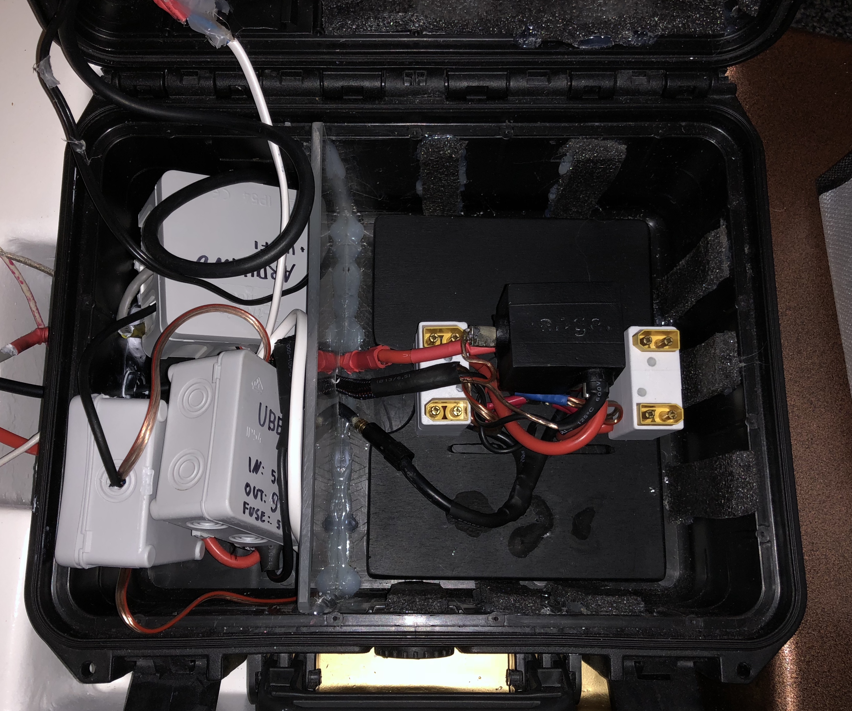
Seriously though nice progress, the waterproof cabling can take ages. I took me a whole weekend to assemble the esc and battery box with all cable glands.
Waterproofing is a pain! And all those cables drive me mad. Lots of time and work with little visible progress.
Left to do are two temp sensors, the plugs for the VESC and the safety cutoff.
Looks like my VESC is bricked. Hopefully they can repair it. I am sooo close to do prop testing. Very frustrating when things go wrong that you have no control over. While I wait, ill build a test stand and some props.
can you tell what you did?
maybe we can help you? Spareparts needed?
Maytech has just launched a new 100A vesc based off the 4.12 Vesc. Maybe they’d be interested in testing it on an efoil…
1 Like
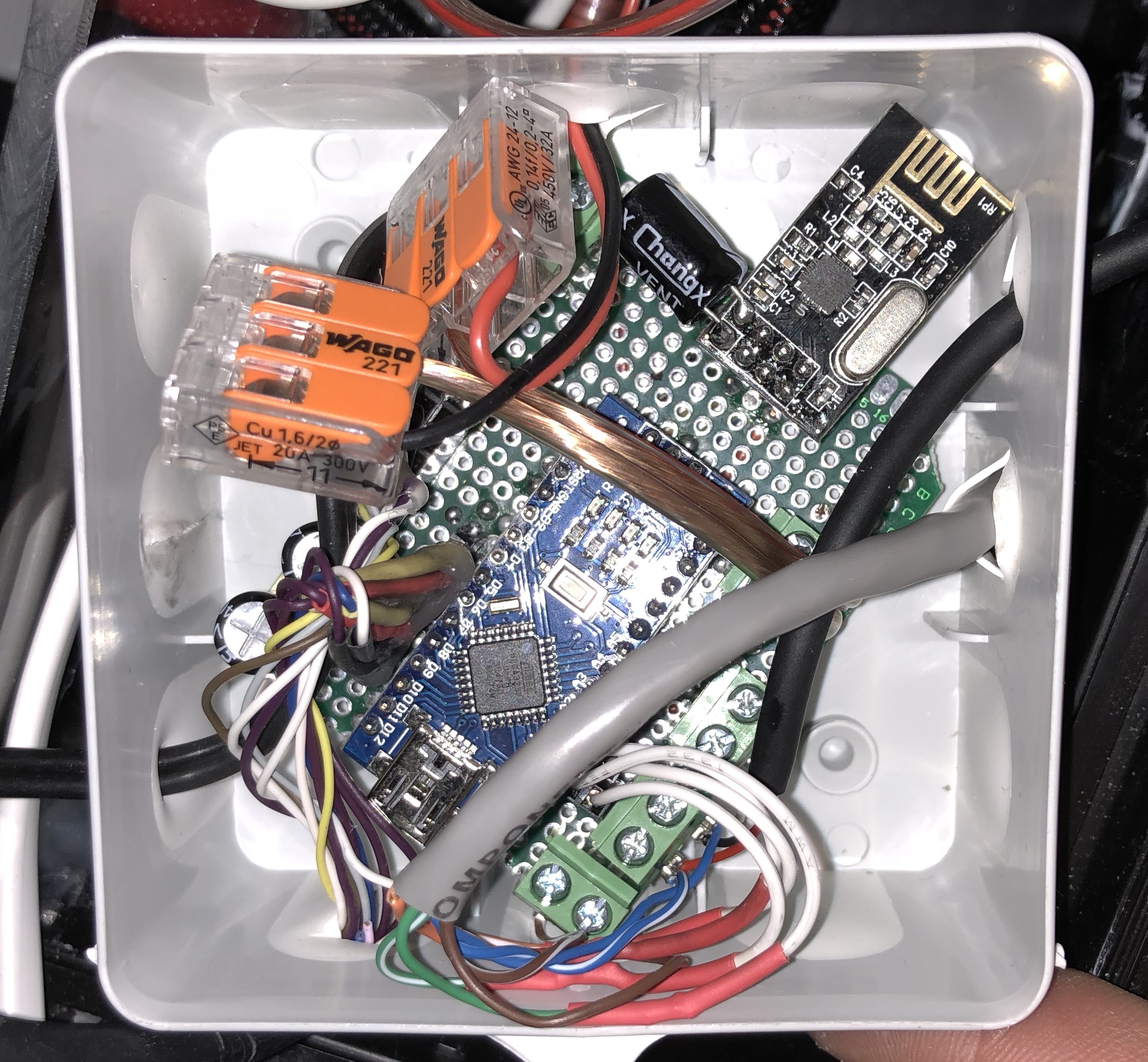
I connected the Arduino to the VESC. I thought this was straight forward, but its not. The VESC has 3 pins, GND, 5V and Signal. I connected the three of them to the Arduino and apparently the Arduino and the VESC power supply were fighting against each others. How am I supposed to know this stuff? I doubt I am the first person that did this. Not everyone building an eskate studied electronics and there is no warning anywhere that this is a possibility. A simple instruction would be all that is needed. I got the VESC because I thought it was the safe option, but it turns out not the high current or salt water, but the tiny Arduino killed it : /
It is thought that the DRV on the VESC is broken. Trampa recommends sending it to Benjamin Vedder who developed the VESC. I am quite frustrated. This will take a long time and cost even more money. The DRV has something like 20 SMD pins, which I cannot repair at home. I might try getting a Maytech if thats the cheaper option than repairing the VESC.
Well, sounds like you killed the 5V regulator of the DRV.
Martin Sprusansky offers flatrate repairs at 35€.
http://electricskateboard.repair/index.php?id_product=12&controller=product
Does take the time to ship to slovakia and back, but he might have the parts in stock and can repair it in a couple of days. I would just send him a mail and tell him your situation. He will tell you your options and give a recommendation.
Well, one thing is: never create loops, not at VCC, not at ground.
Loops at VCC leads to power supply fight (in your case DRV vs arduino regulator), loops on ground can do funny things to transmitted signals.
If you are sure what‘s wrong with it, it‘s actually not that hard to switch the DRV chip or even the processor on the vesc. I have modified my VESCs quite a lot and killed some chips while testing my mods. If you use loads of flux and a hot air gun ( temperature control is a bonus) it‘s pretty easy. I assambled mine from scratch and repaired them twice, always worked on the first try. Just don‘t try to reflash the firmware while your lathe still drives the motor connected to the vesc, that for sure kills it instantly ![]()
Edit: If you want to do this you can ask me for more details, by testing with 3,3V I mean only this voltage without connecting any other powersupply. /Edit.
If you want to debug it further, you could connect a lab power supply with exactly 3,3V to the 3V3 rail on the vesc and see if it draws excessive current (set current limit to e.g. 300mA or less). If it does not draw excessive current, you should be able to connect to it via USB. Obviously it still will not drive the motor then. If you check the schematic I posted earlier, check D4 and D5. Especially the protection diode D5 will likely be the one damged if any as it sinks all current your UBEC can supply in order to keep 5V. If that one is still good, remove the DRV chip and supply 5V to the board and check if you can connect via USB again. The DRV8301 is about 15€ shipped (single part + shipping incl. VAT).
I think it is designed to be connected to a regular RC reciver, which will be powered by the vesc. I think most ESC’s with internal reciver powersupply would not have liked that connection. You built a more advanced version, but hey it‘s R&D, sometimes one forgets to connect stuff, sometimes i have connected to much and let the magic smoke out. Keep it up, it‘s really cool when the first prop hits the water!
1 Like
Thank you! I found somebody from the netherlands who offered to repair it. So it is on the way now. Not sure if that person has an account here or wants to stay annonymous. I am quite thankfull though!
I saw some pictures of the disassembled VESC 6.4 and they use thick thermal pads to bond them to the aluminium. Surely there has to be a more efficient solution.
1 Like
Just in case the repair doesn’t work…Here is a much cheaper version for you FSESC 6.6 With Aluminum Case and switch | Flipsky – FLIPSKY
2 Likes
I havent, but I think there may be some in the E-Skate crew that have. I know that Maytech have also just released a VESC capable of doing 100A continuous which I am more interested in…
There are also some guys in the robot world that have 200A VESC’s but they come at a hefty price!
Thanks for the tip. Ill keep it in mind if I need an alternative. What I don’t like about all of these is that they transfer the heat over thermal pads.
Hi Max !
From what I’ve read on the forum, you are the only one who iis trying this motor:
https://alienpowersystem.com/shop/brushless-motors/aps-70110-outrunner-brushless-motor-100kv-3200w/
100kV 3,2kW from APS that is already waterproofed (pretty handy !).
It looks like they put a Outrunner inside an aluminium tube.
Have you had the chance to open it to see if it’s filled with oil ?
I’m tempted to give it a try too but would love to know how they ensure the cooling.
Congrats again for your setup !
I have one of those too, but still untested. It is a stainless steel tube. I don’t think there is any oil inside it…
I tried to open it by unscrewing the bolts, but everything is glued together with silicone, so I was unable. I don’t know how it looks like on the inside. I asked Bruno from Alien for pictures or dengineering drawings but he couldn’t provide any.
So It would be cool if somebody could provide more information.
Thanks Jezza and Max !
When you shake it, do you feel like any liquid is inside ?
I don’t see how it could be cooled otherwise.
If no liquid, 2 options:
- It’s not gonna get so hot
- It’s gonna get really hot until the motor fail
Maybe you can also measure the power consumption with no load on the axis and compare it to other values found on this forum (I think there are curves available on the “Direct drive with outrunner” section).