Sorry for the long wait, i can post them on saturday.
4 Likes
That would be great thanks!
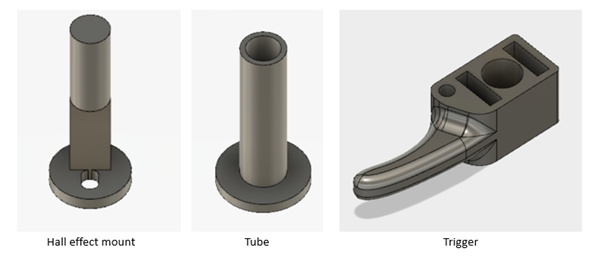
Finally, here is the latest trigger based controller.
the compartment is quite large. This is to make it simple to fit electronics, it also features screws and an o-ring seal to make it disassemble. A 18650 cell will fit in the handle.
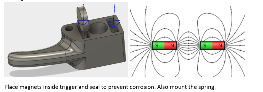
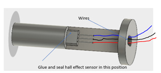
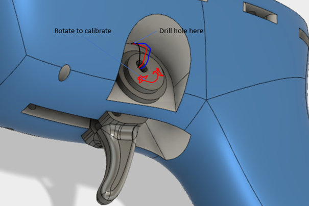
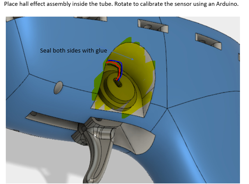
The trigger system is based off a linear hall effect sensor (SS495A) with analog output. And uses two circle magnets 2.5mm*10mm. The reason it is made this way is, easy 3D print, easy waterproof, and compact. But there are some drawbacks, it needs calibration, and software averaging to make it smooth, as expected when working with hall effect sensors.
Part list:
electronics:
hall effect sensor: SS495A https://uk.rs-online.com/web/p/hall-effect-sensors/2166247/
18650 cell and charge circuit
magnetic charger https://www.ebay.com/itm/Braided-Magnetic-Lightning-USB-Charger-Charging-Cable-For-iPhone-Samsung-Type-C/302538828114?hash=item4670b82952:m:mAhwvjjycSGFffF5j7wAa0A
charge modulehttps://www.ebay.com/itm/5V-USB-3-7V-Lithium-Li-ion-18650-Battery-Charger-Charging-Module-DIY-Power-Bank/122497098256?epid=879304955&hash=item1c85656210:g:xXkAAOSwQ59Za1~C
Magnets: https://www.ebay.com/itm/10-20-50-x-Strong-Neodymium-Cylinder-Rare-Earth-N35-Fridge-Magnets-10-x-2-5-mm/172757804339?hash=item28392ae533:m:macIMepnsrWUoxfZ4h_tdTg
Springs: https://www.ebay.com/itm/Wire-Diameter-0-4mm-304-Stainless-Steel-Extension-Tension-Spring-Hook-Loop-Ends/222772807587?hash=item33de4b47a3:m:m0b9MLQxqnGWfKbW-oLgvgw
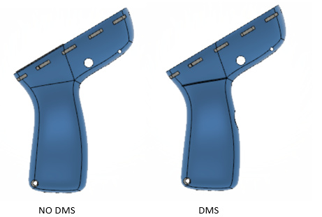
DMS: https://uk.rs-online.com/web/p/push-button-switches/8418452/
ON/OFF button Chrome Glow 12V Waterproof Push-Button On-Off Switch with 12" Leads | eBay
O-ring 2mm cord https://uk.rs-online.com/web/p/o-ring-cords/1381600/
Metric stainless screws and nuts 250pcs M3(3mm) A2 Stainles Steel Allen Bolts With Hex Nuts Screws Assortment | eBay
use M3*12mm 11x
use M3 nuts 11x
Note: the DMS buttons are quite expensive, but they are truly waterproof! Most momentary IP 67 buttons are not designed for submerged operation, and will leak.
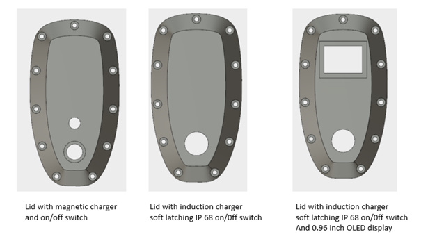
the on/off button is not ideal. Use silicone or an elastic glue when mounting it.
a soft latching system is better
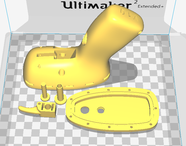
The current STL files.
Bodys
Lids
Trigger Assembly
Print settings
100% infill,
print like this
All files are here!
A quick guide.:
21 Likes
Very generous to share files when so much work is put into it.
Later I will dig into this.
Right now I have a question about the thrust bearing.
My feeling is that for the thrustbearing to take any load off the gearbox the shaft coupling would have to be on splines on the gearbox or the shaftcoupling would have to be pre-tensioned against the gearbox otherwise when the axial load comes from the propeller the plastic part that support the thrustbearing will compress a little and the gearbox would still havee to take most of the axial force.
If the gearbox had a axial play of say 1mm then I can see it work… Did I missunderstood something in the design?
amazing work! how you get you 3d prints waterproof?
1 Like
You are correct, a splined shaft would be much better to take the axial load. The gearbox we used on the V1 had some axial play (0.5mm), so a combination of preload and axial play made it work. On our newer version we have changed to a spider coupling with the prop axle on individual thrust/axial bearings.
the walls are quite thick, also a epoxy coating will help.
Thank you, it is great inspiration.
Thankyou for sharing @Hiorth The remote looks great. What model arduino do you recommend to use with the remote.
Hello
Congratulations for your work, it’s really excellent, can you communicate the list of arduino electronic component or link, thank you in advance.
You can use different type of chips as long as there is room for it. We have used arduino nano, combined with a bluetooth chip (hc05 if i remember correctly) . These chips can be dual waterproofed with large adhesive lined heatshrink inside the controller, more convenient than potting if you like to reprogram the chips later on.
1 Like
Hi, thanks for sharing the STL-Files. Realy great job!
I’ve seen you created already a version V5 with a thumbwheel from RS. I’m going the same way cause it’s already sealed and together with the EXCELWAY remote pretty small. Would it be possible to share the V5, too?
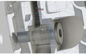
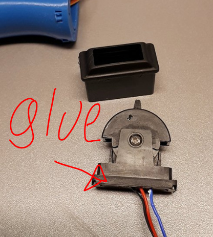
Yes, I can see what files I have maybe draw some thing. But I don’t have time right now. IF you are using the sensor form RS components, you must screw it apart and apply glue or silicon to make it watertight. it is fairly obvious where you need to apply glue when you open it.
thanks !
1 Like
Thanks:) The thumb switch from RS is not that good, its not waterproof (the switch is) but not the casing. The switch also gets slow from salt water, and the magnet is not Shielded (so it will corrode pretty fast). Had issues with the switch jamming in throttle from time to time.
1 Like
Thanks a lot for your worthful help. It’s amazing, you tried a lot and you have a large know-how. 
I will open the switch and check what and how to do. Hope I will find a way. If yes, I will respond.
Anyway possible to get the old STL-FIles from V5?
1 Like
Thanks a lot for sharing the files. I’m in the process of building one, printed the body and trigger and I like the ergonomy, it fits my hand. Managed to install the hall sensor and transmit with Arduino Nano/nRF24.
I would like to use a bigger display and a different power switch. It would be useful if you could add the lid in a more editable file like step. Maybe just with the holes for the screws so people could draw openings according individual needs (display, LEDs, magnetic connector, etc).
Will upload fix a Step file for you to alter the lid for a different screen, just need to find it. Please share a picture when you are finished with your remote ![]() Would be awesome to see how people are modifying the remote for their own use.
Would be awesome to see how people are modifying the remote for their own use.
WARNING TO (all) people that are building this remote: There should be at least one more mechanism that stops the board if you fall off (LEASH, preassure pad, or similar) , the dead mans switch alone seems to be insufficient. If you are not focused, its easy to forget to release the throttle when you fall (the dead mans-switch is mostly if you loose the remote). Had the board run into me after a fall the other day.
@sat_be
her is a link to the lid ![]() download link in top right corner.
download link in top right corner.
also added to
2 Likes
Remote looks awesome good job, i am just about to start to look at making mine. I am new to arduino programming. Are there sample codes online codes to connect 2 auduinio nanos together with a wifi / blue tooth connection the remote to the motor controller or can you share your code?
There are a few samples in the thread : "DIY Waterproof remote"
for both RF and Bluetooth i think…
1 Like