So you suggest that i should just get rid of the bearing?
In theory two bearings on the shaft and a flex coupler would be good. But I have not tested the setup you have drawn above. That‘s why I only want to remind you to think about if a wobble because of the 3 bewrings cold be an issue. Sorry, I know this doesn‘t answer the question.
Did you mean the two motor bearings or?
And is this a flex coupler?
I was originally going to use this but if the other has its advantages

But thanks for the heads up with the wobble issues 
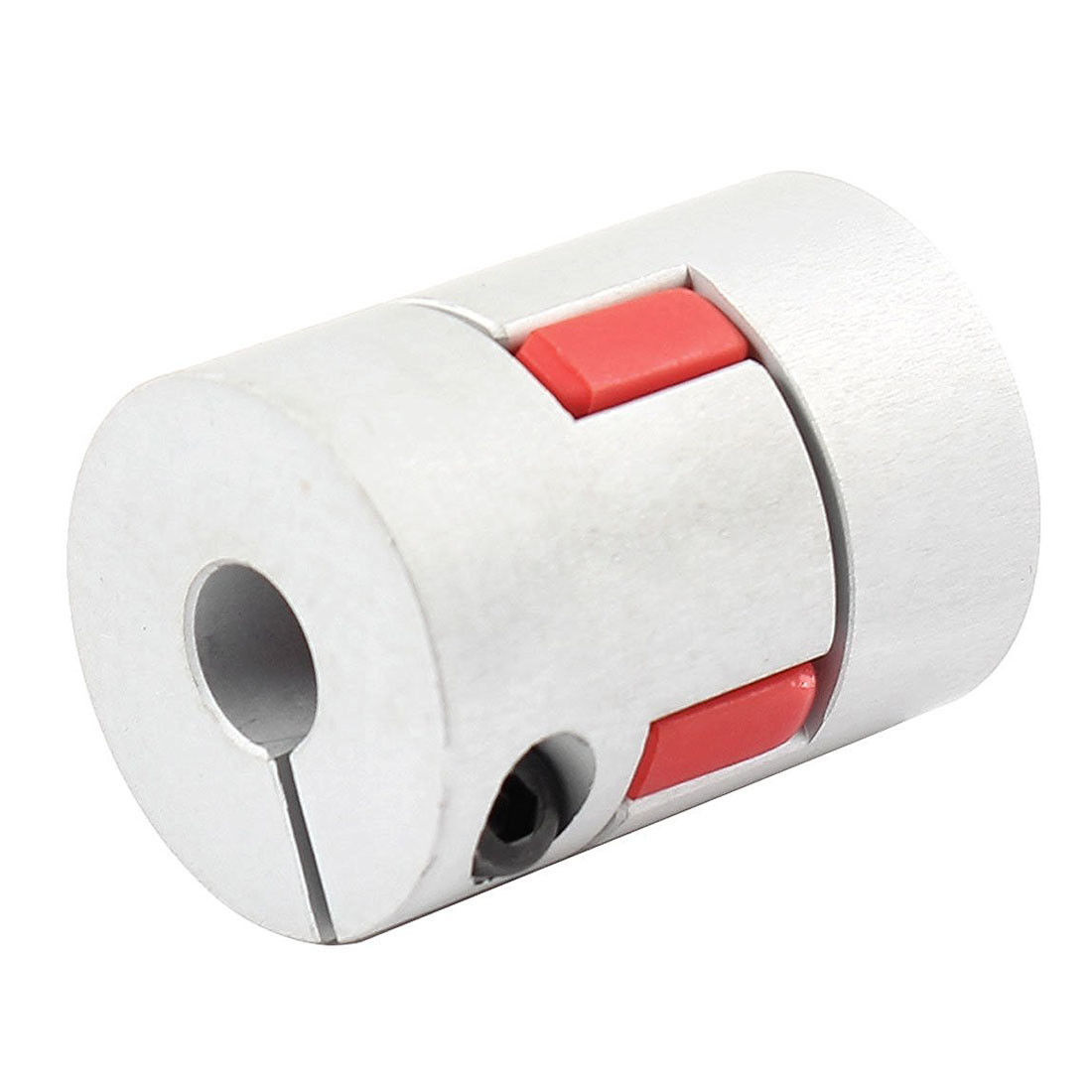
The upper one is called a jaw/spider coupling and is meant to accommodate misalignments by a flexible part. I think it is a good idea, but you will need a high quality one, plausibly rated for the torque you need. This type of coupler has already failed, like about every coupler type tested. The blue one isn’t flexible and can make your seals leak. Also this set screw fixing mechanism failed repeatedly, you need more than hand tightening.
So basically a strong coupler with room for some flex for wobbly shaft.
@Flo & @Benjo
If i do not have the last bearing wouldnt that mean that if the shaft is woobly the seal is going to take the pressure?
The Hiorth Brothers have a textbook example for the bearing setup. They have shown a drawing here: Shaft couper solutions/recommendations - #18 by Hiorth - Propulsion System (Motor, Gears) - FOIL.zone .
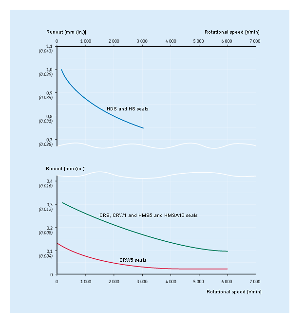
The straight couplers you showed with setscrews can be a major source of misalignment themselves, in addition to problems with slipping setscrews @Benjo mentioned. Such fixed couplers really only reach sufficent alignment of shafts when there is a defined clearance( like H7/h6) between coupler and shaft. If the setscrews do more than prevent rotation, a misalignment is caused. This misalignment causes the wobble when you add a third bearing, even when your shafts are otherwise perfectly straight. However I still think you need a bearing close to the seals to prevent vibration and water entry, you can look up some numbers here for example: http://www.skf.com/binary/12-14885/1__en__rss_4d_tcm_12-14885.gif
I m using really cheap Jaw/spider coupling from amazone, more than 10 times without any problem. You just need to improve it. Prevent rotation of coupling on axes by adding a washer.
Add small cylinder 3d printed in the middle to prevent bending of cross plastic part.(in red on previous picture)
@Gobbla good to know, thanks!
@Migro I would be interested to know why you settled for a jet drive? Are you aware that this concept is one of the most expensive, probably the most inefficient (less thrust, less ride time or higher battery cost) and relatively complex (you will need some machined parts or expensive off the shelf impellers etc.)? Just curious 
@VeFoil kinda convinced me. And I just thought safety and simplicity. No gear. Since I see people stripping gears and thats a cost in it self.
It just seems simple with a motor and a propeller. And I as many other also own a 3d printer. Would you say that the other option is cheaper?
Safety is a big plus, sure. For me personally the negative points outweigh this.
Having a CNC or access to one would be a big plus as those impellers are pretty pricey and can’t be printed due to the high speed (they break or at least bend, reducing efficiency dramatically).
A geared drive is also expensive and has many drawbacks as you probably know.
My favorite is a direct drive with a wet outrunner, it is the simplest and cheapest as you basically just need the motor and a prop (as far as the propulsion unit goes). You can take a 10€ commercial prop or print one. Then just fix the motor with a simple printed mount and do something against corrosion and hydrodynamical losses (epoxy, plastic spray) and you are good to go, no seals, no added bearings, nothing that can fail apart from the motor - and it doesn’t fail if you leave it some space to dissipate the heat.
One downside regarding the safety aspect, it is a bit harder to design a duct for this propulsion type, as the whole prop-motor combination spins and you would need to attach it further at the front.
Definitely an option seems pretty straight forward except for the anti corrosion thing.
It doesn’t get much simpler than this concept it’s basically attaching a prop to a motor and the motor to the mast, if you did this and nothing more it will already work. The anti corrosion treatment can be anything from very simple to involved, depending on how long you want the motor to stay pristine.
Just take a look at what others did, the 80100 motor seems to recently get much attention, I just received mine as well.
If you want to build a cool jet drive that is awesome too, just will need some more work and tuning to compete 
Will check it out.
Good luck with your build looking forward to seeing some progress
1 Like
Yes I meant something like your draw. The section design you posted here is candidate to a bad failure, because it’s delivering thrust force straight into the motor shaft, so you either need angled roll bearings on your motor, strong enought to cope with propeller thrust, or you end up seizing the motor, losing sync, burning it or worst stripping a gearbox the same as I did!
In my opinion, the only way is the shaft pushing on the solid body of the pod or motor, thru a needle thrust bearing. If the shaft is supported by two ball bearing, well aligned, wobble should not be an issue. Then the coupler could be whatever you like, just able to cope with the torque and rpm.
So you’re saying that i need a thrust bearing. How should this be connected.
Doesn’t one of the washers on a thrust bearing need to be fastened to on of the objects to take the pressure?
As i can see a lot of people have been 3d printing their mast and wings i thought i could do the same. Even though i dont see that many people coming with updates to see if it works.
So i found a shape on some existing foil somewhere i used for reference. And made it easier to stack in 10cm sections.
I just dont know if its enough with plastic as a guide and then fiber glass?
my first homemade foil was done around a core plywood… can’t have been much stronger than plastic… most of the stress is taken by the fiber shell around it, just make sure it’s thick enough…
glass can work as well as carbon, it might just be a bit thicker and les stiff…
1 Like
Wow great video 
May add some space for something to stiffen up the mast.
You seem to know what you are doing when making the board 
you can use carbon fiber tubes, light and stiff, and not too expensive… or design some kind of ribs going up the mast like a few of us did to make 3d printed wings here…
actually, not at all, that was the second board ever I made
I disagree about het drive requiring more tuning. I think it is all relative no mater if you use direct prop or jet. If your really committed it would take a lot of tuning to get that direct drive prop and the duct tuned so the motor is not over drawing extra current/overheating/wasting battery power. The smallest 1-2% blade or duct tweek will change performance 10-30% we found.
As for 3D printing the masts, i know many companies are putting in aluminum incerts to strengthen them Or making them solid to avoid bending which we have had once already with an aluminum mast. I cant see 3D printed lasting long unless they are done really well with a carbon wrap and reinforcements. You can get amazing masts like the slingshot ultra strong for line $100. There is no need to make one inmy opinion.