They aren’t even normally that long, but easily cool the ESC and motor. One side is cut with opening facing the direction and the other exit in the opposite. If you watch a video of a boat, you can usually see the water shooting out from the boat. Here’s a youtube example.https://www.youtube.com/watch?v=it5LY9hLtkQ
I would think a similar design would be adequate for a foil. Just need to run longer tubing.
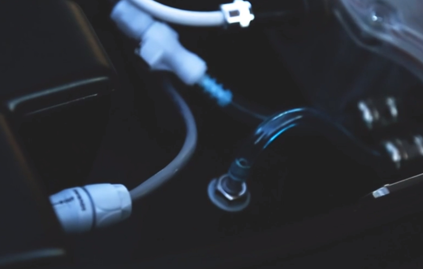
That’s a really informative video. Does anybody know what connector is used to connect the battery? Looks heavy duty with built in on/off switch – at least I assume that is a connection to the battery. Also, what is the smaller grey connector for that you see him plug in?
LEARNED THIS IS NOT GOOD FOR HIGH CURRENT - avoid if using more than 80A continuious.
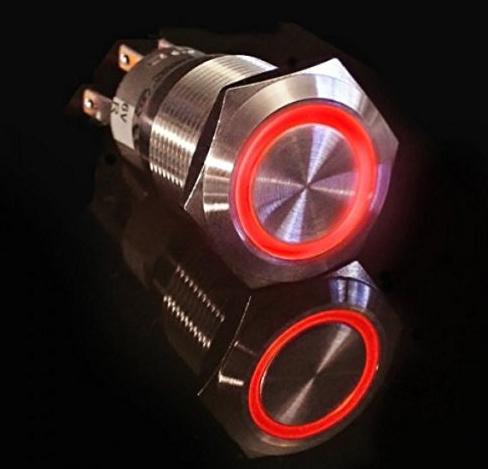
Cool video and looking setup on that Lift board. I like the convenient and sleek on/off switch.
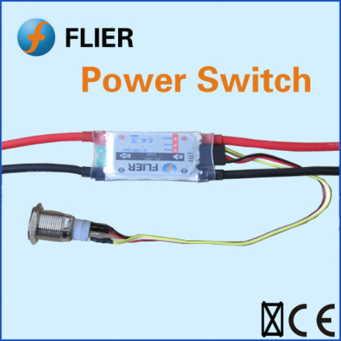
Flier makes a 120A and 300A Power Switch that works as both an anti-spark, and power on/off. The link is to their 120A. Its $42 plus shipping and is a nice touch. https://www.aliexpress.com/item/Small-remote-control-for-skateboard/32718274135.html
How long were your cables?
I guess there are just a bunch of Fets inside, long cables + high frequency switching kills every Fet without caps for buffering in front. Thats why you should have short ESC power cables or a bunch of caps.
Luckily, nothing else burned or broke down, the strange thing is that the 200Amps fuse did not blow!
I have a EagleTree to monitor the Amp but haven’t connected it. I guess it will blow too, it’s rated only 100Amps.
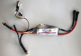
My cables where: Lipo-10cm-200Amp fuse-10cm-PowerSwitch-10cm-ESC-130cm-SSS Motor
The Eagle Tree is actually rated for 150A if you have their heavier leads, but still that system will be stressed and run hot I feel. I also have Eagle Tree, have not installed it yet either. My plan is to just use it for testing and get a feel for things, not something I want to have permanently installed in the system.
Your SSS motor, is that 500kv (116A) or the 360kv (93A)?
Either way though really… 300A switch should handle that current.
The MGM Controllers up in this range all run 6AWG wiring and cost $800-$1200 USD, but I do feel they are built to last. I sent them an email just now asking if they have any high current power switches for ESC’s… Ill post it here if they do.
Ya, I thought of that also, but was not sure how it would affect things.Maybe someone here can chime in?
My guess is AMP/current would not be correct, maybe times it by two?
I have the Screen, GPS and motor RPM sensor which should still run accurately (I think). maybe worth an email to Eagle Tree see what they say?
Eagle tree said GPS, screen, and motor RPM sensor would still work fine running on one battery/6S but they would like to see how it would be wired up with a diagram to confirm. Looking at how eLogger V4 is wired, I’m not exactly sure how it would be wired when batteries are in series to only get half power going through it?
Depends on the resistance of the the Eagletree, in theory you draw the same amps of each battery, but it already differs if you the cycles of the batteries vary or if you use different brands.
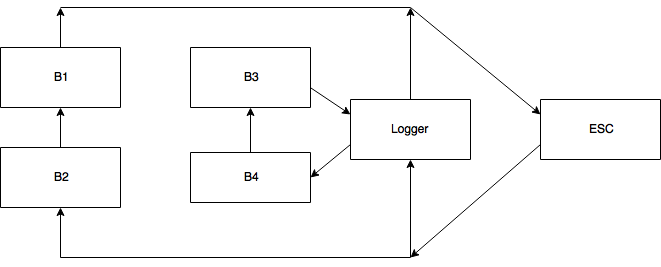
Exactly, if we want 12S output using 6S batteries, there is no way to decrease the current trough 2 batteries joined in a series. To decrease the current we have to join them in parallel, and to get 12S we will need 4 of them. Wiring will look like on the following diagram.
Correct, in parallel connection will allow us to get half of the current going through the logger (approximately, it will be a bit less than a half coz the logger has some resistance), and in series to get double voltage from 6S batteries. It’s all assuming that all batteries are exacly the same make/model, age, charge level, etc… It’s not a big deal if they don’t, any large battery has a similar schematics inside, it’s just harder to estimate current through the logger if the system is not balanced, and you can’t rely on current measurements from the logger in this case.