Vesc will be definitely the way to go, as soon as max power/overheating issues would be solved, anyway, regenerative function can’t exist if a solenoid cut the battery connection!
Trigger drillbit style it’s a great idea, with a very reliable remote
I drew up the electircs plan today. I am keen to hear your opinions on this.
Things that are missing:
- thermometers
- ESC to Arduino connection
- status LEDs
- maybe the UBEC vs a 12V battery
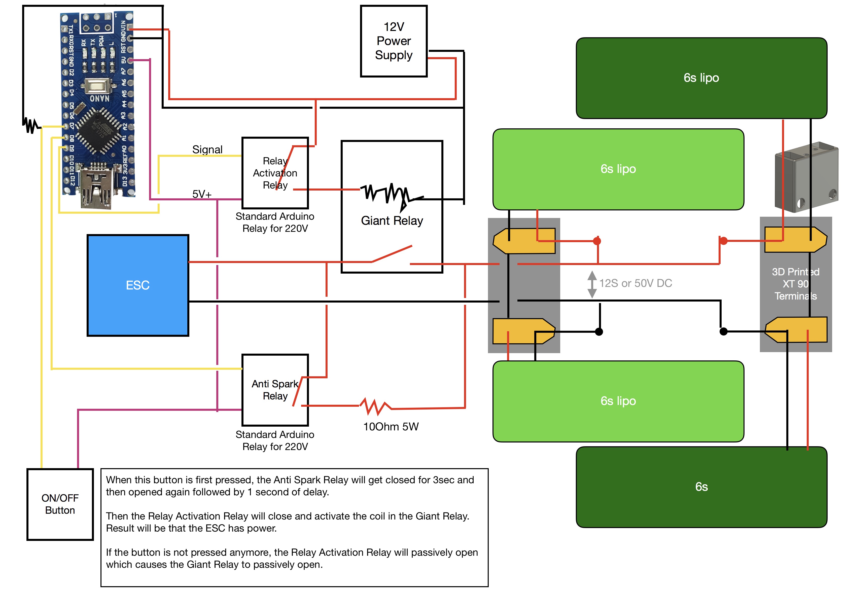
It could work! Small relays protects the electronics. Basically, the first stage relay works as capacitors “precharge”? Let’s see how it goes. I wish to test the Vedder antispark soon, so we can compare these solutions.
Yes, the anti spark relay slowly charges the capacitors.
I just tested the relay. I run it at 9.5V even though it is a 12V relay. I measured 1A of current. Unfortunatley, it reached about 90°C after about 10min. That is not acceptable. Any ideas what I could do? Would 12 or 15V help?
The datasheet to your relay from I think I found the right battery relays - Electronics (ESC, remote, batteries) - FOIL.zone http://www.albrightinternational.com/wpcms/wp-content/uploads/2015/07/SU80-Catalogue-Sheet-v8-04-13-Electronic-Issue.pdf says “coil power dissipation: continously rated types: 7 -13 W”. So this is a little bit expected. Maybe you can reduce the current through the relay after it is engaged, this would reduce your 9.5W of losses and thus your temperature. In the datasheet it states that it will switch on with 66% Us (66% of 12V) at 20°C. And it will drop off only below 10 - 25% Us so you could reduce your losses quite a bit.
My relay uses 273mA continuous and is completely waterproof rated 350A. Just find a better one.
1 Like
Nice, but at this point, I have no space left.
So you say I should lower the current after it closed? How could I do that?
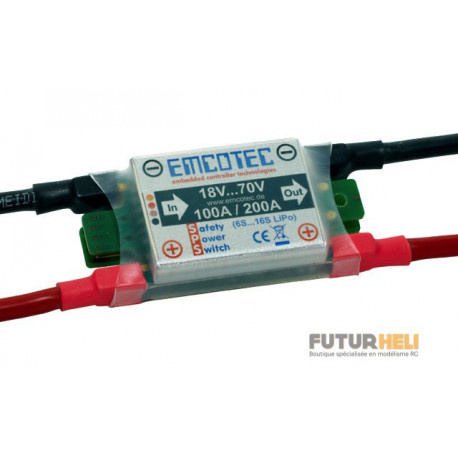
Hello
someone know this type of switch, I want to use it! but I do not know if it’s good? for battery from 6S to 16S Lipo, 100A / 200A.
That was my idea last night, you could add a series resistor, but this would lower your losses only a bit as the resistor produces some heat then.
I would try to use one of those cheap 1€ buck converters / step-down converters from ebay and apply a lower voltage to the relays actuation coil. The relays coil is in static use like a resistor, it will draw current according to Ohm’s law. The the first buck converter I found is from china, but you should be able to find one from europe with reasonable shipping times.
But this is only an idea now, I don’t know how much you can reduce your temperature by this. But 25% * 12V = 3V and your coil has a resistance of 9,5V/1A=9,5Ohm. It should lower your losses to about 1W compared to 9,5W. You will have to test at which voltage your relay really drops off though.
Edit: You could get the same 3V across the relay and the same ~0,32A current with a series resistor of ~20Ohms but it will produce about 2W of heat.
You are using arduino to close it?
Why not use PWM signal?
Start with 100% Duty and after it is closed you can test with how low you can go, but I guess even 50% Duty should be enough…
Edit: only works if your relay closer relay is not mechanical.
1 Like
That’s an even better idea, just a little more complicated than adding a second relay if you don’t love electronics ![]()
@MaxMaker if you remember my schematic in Pacificmeister Build Info and CAD Sources - #298 by Flo - Builds - FOIL.zone you should be able to do this.
I don 't that much yet in relay but what about to use a normally closed relay and then apply power to open it and cut the battery?
Maybe even a simple transistor (like the 2N2222A) can do the job. Depending on the current you need for your coil…
Well, I can turn the UBEC down to 8V. And then make a relay divert the current through a buck converter at maybe 5V after the relay was closed. But with that I can only change the voltage. Will the coil not automatically draw more current at a lower voltage?
I could also take out the winding and double the number of loops with thinner windings.
The relay coil acts like a resistor to DC voltage. More voltage more current, U=R*I basically. Just some nasty spikes from the inductance when switching off.
Don‘t modify the coil, it‘s not worth the effort.
Would that not mean that more voltage equals less current?
I just did some testing at the lab power supply.
Relay Closes at 8.5V and draws 0.5 A.
At 9.5V it draws 0.56A, but I measured 1A with the UBEC at the same Voltage. Is th UBEC a current source???
At 5V it draws 0.29A
At 3V it draws 0.17A
At 2V it draws 0.12A
Below 2V it opens up again.
So Flo is right, I could save a lot of energy. But why does it consume less current with the lab power supply than with the UBEC? 1A vs 0.5A.
no, R is constant so I=U/R
less voltage, less current
how do you measure it? and where, before BEC or after?