With cold weather here and so little data available I thought it would be a good idea to build a flume for testing motors and propellers. Don’t laugh at what I built… I had a few tight constraints. 1) materials had to fit in the back of my car, 2) The flume has to fit in my two car garage (when it is not in use) and with two cars inside the garage too.
Mike (fancyfoam) and I tested it for the first time this evening… looks like it going to work. It’s not perfect but with a few improvements we should be able to do some good propeller testing and development.
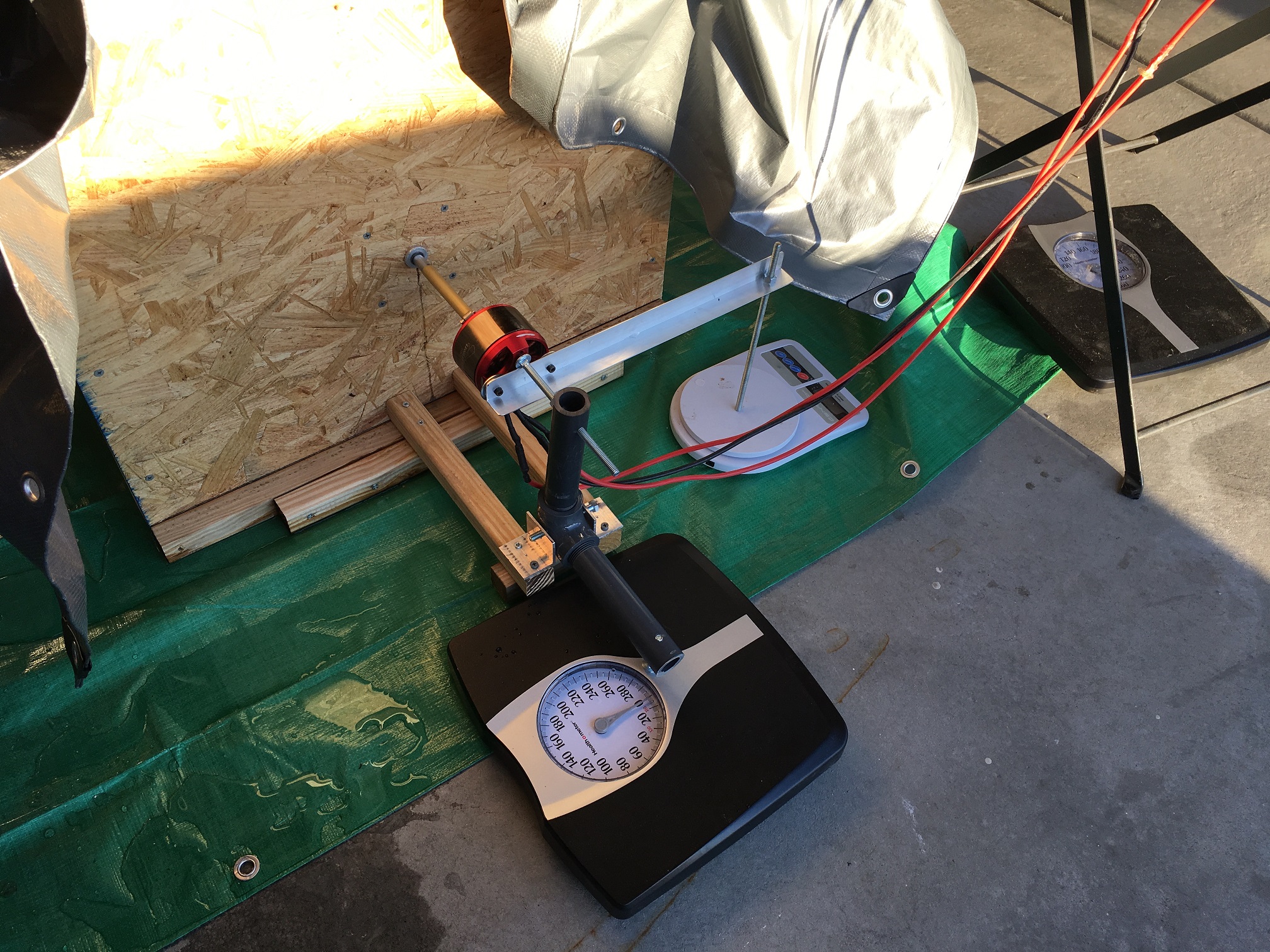
So far the flume can measure thrust, torque, Volts, Amps, Watts, with future measurement of motor speed and possibly water speed.
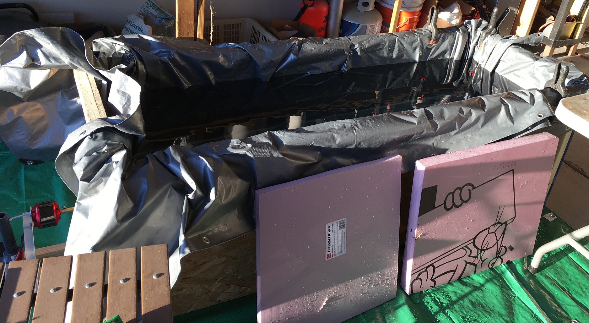
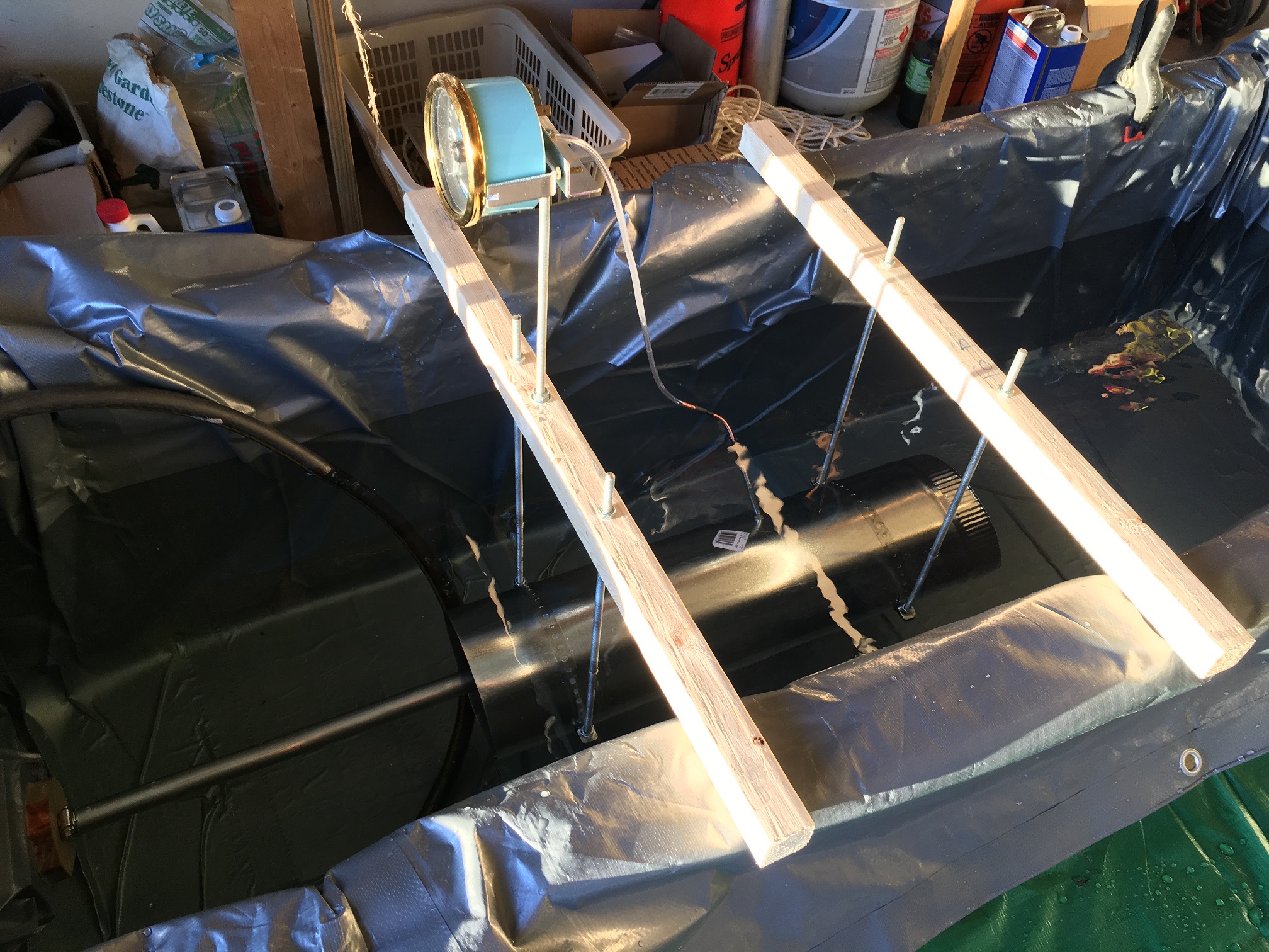
Below are some photos of the flume.
The tank is a simple box with a tarp for a liner…redneck swimming pool style.
Here are some results from the first set of tests. At this point, I don’t know how accurate the data is but the relative performance differences were obvious.
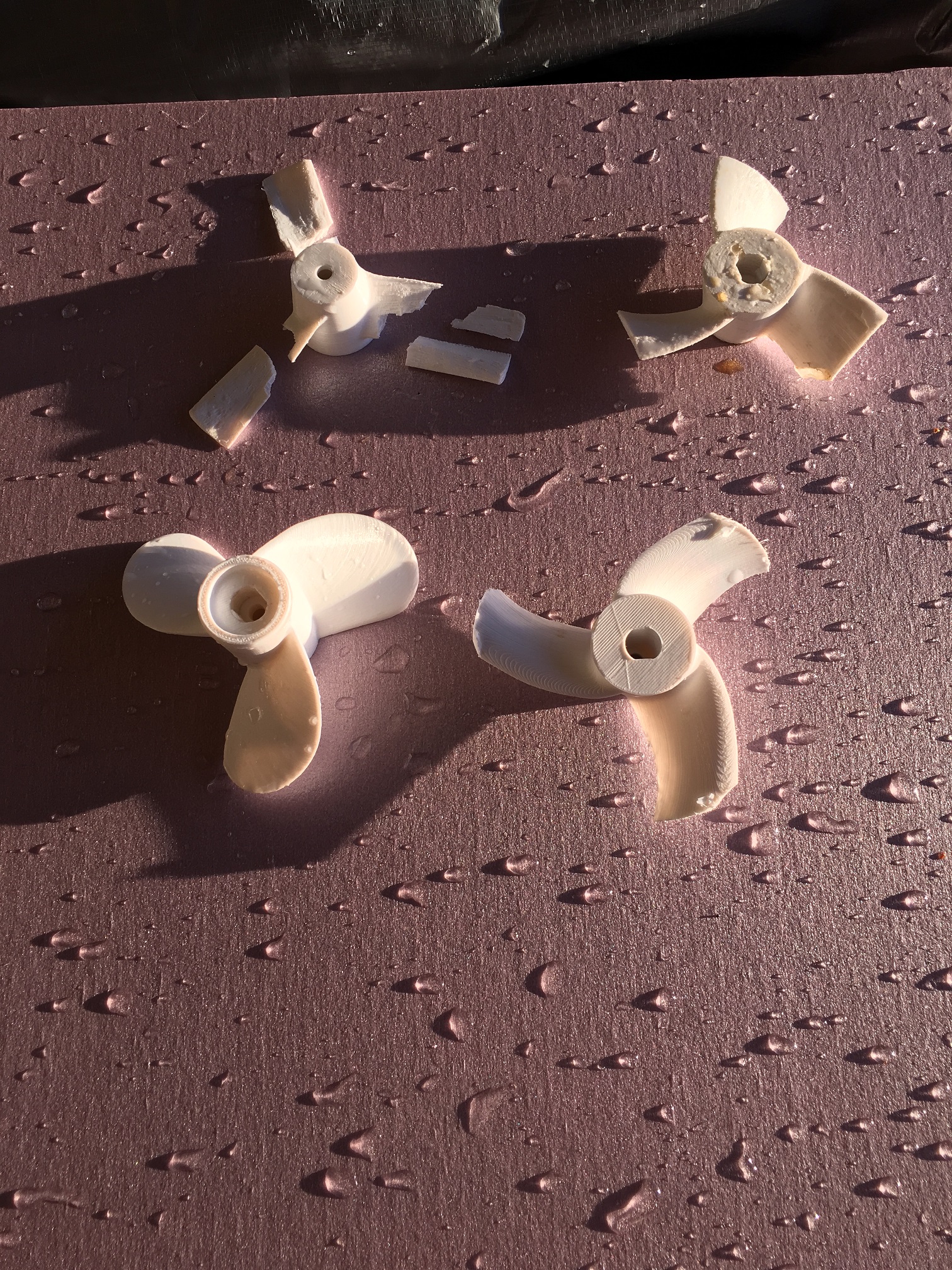
We tested four propellers 1) High aspect ratio based on pacificmeister design -10 degrees of pitch 2) Same as 1) except lower aspect ratio (wider) blades 3) pacificmeister design cut down to 3.5" diamter and 4) A scaled down outboard motor propeller…Mike can share details about this prop design.
Test results are that the scaled down boat propeller (bottom left in photo) consumed the least power for the thrust provided. We didn’t expect this and we were quite surprised.
The thin blade high aspect ration prop broke at higher power.
This may take a while…internet service has been really bad last two days. Cutting out every few minutes.
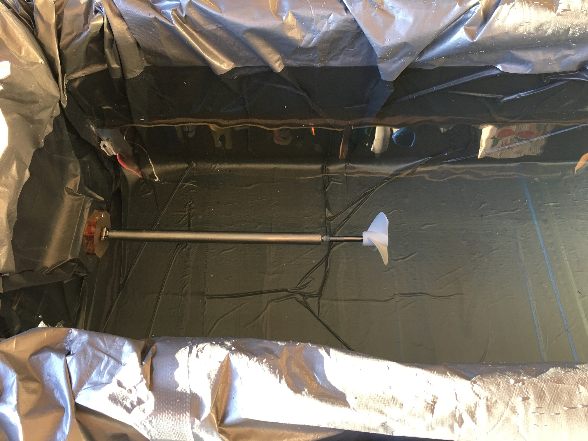
One objective of the testing is to get thrust/power data at cruising speed. I built a test section that fits around the prop that creates a test section. With a pitot tube and a boat speedometer I can do some dynamic thrust testing. In today’s test the tube was too big and the velocity shown was low. By selecting the correct diameter test section, I should be able to achieve realistic flow velocity for testing cruise performance.
Tube slide around propeller to form a test section. The pitot tube is placed a few inches ahead of the propeller.
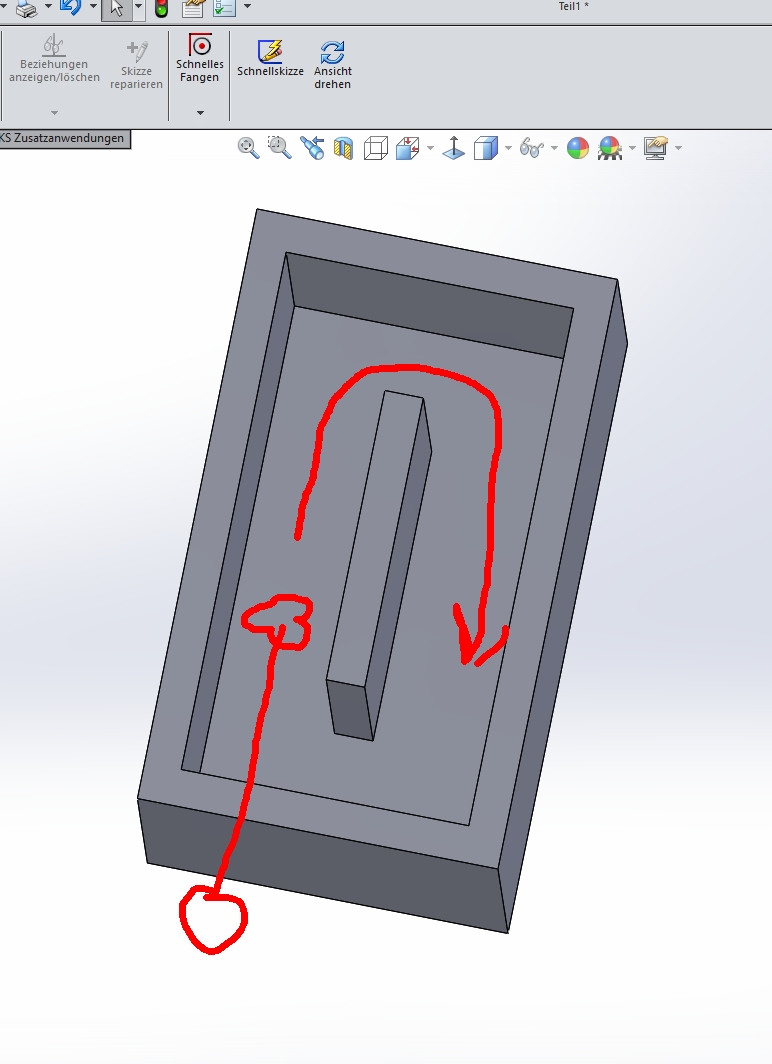
Nice. Testing is alwyas good. Al results you get are static, maybe a liitle difficult to “translate” them to driving conditions. Would it be better to add one wall in the middle of your pool, to get the water circulating? This would simulate a “moving” prop.
I am not surprised at all that the scaled down boat prop was most efficient. It makes complete sense considering that they have had years and years of refining gone into them. A normal scaled down boat prop for lower speeds should work well and if you want higher speeds a 3 blade cleaver prop should do the job!
Jezza, Lol, we almost didn’t test the boat prop…no airfoil shape in the blades…we thought it was “too crude” compared to the others we tested.
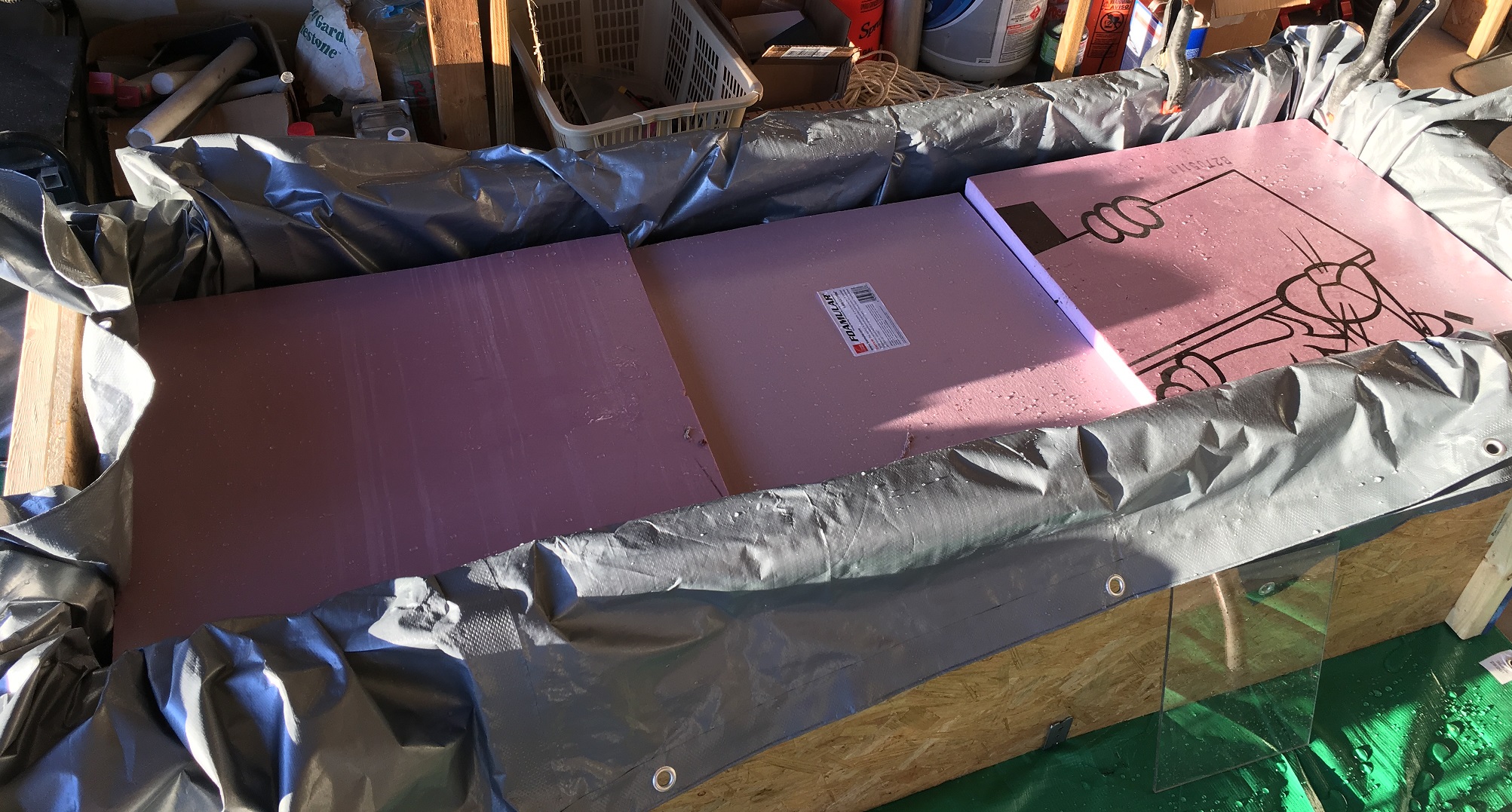
Another surprise was how much these little props churn the water. Also, at higher power, a vortex forms near the front of the propeller and air gets sucked in. We could have raised the water level, but Mike suggested putting a sheet of styrofoam over the prop to prevent vortexing…worked great. Then we added another piece of foam at the back end of the flume to control splashing. Finally we covered the entire flume with sheeets of foam to prevent splashing/vortexing. Not as much fun cause we couldn’t see the prop any more, but the water was well behaved. Next we will add a plexiglass window to the foam in the area of the prop.
In one of my photos above (post #4) you can see a tube added around the prop. The idea is to create a torroidal flow in the flume and to get cruising speed water velocity to flow past the propeller. The 8" diameter tube wa a little too big and the velcocity was on the low side; about 6 or 7 mph indicated. Next I plan to install a smaller diamter test section tube to increase the test section water velocity.
@Winging_it, airfoil’s are really used for low speed efficiency and thrust. Once a prop is spinning at 1500rpm+, you really want a path of least resistance. Something as thin, flat and strong (minimal deflection of blades) as possible. I should send through the files for prop I designed (more like randomly threw together), it would be interesting to see how it stacks up against the ones you have tested…
how about building a loop of 4" waste pipe with a t junction with a screw on to for the shaft to enter on and then perhaps another t joint vertically so you can see/change the prop that way you would get some good water flow and maybe a better approximation
.
Great work! I like the hands on testing, Rough propeller shape could be determined this way with ease. Fine tuning could be done on CFD, and then again tested in the Flume.
It is really great initiative! Congratulations!
Im looking forward to seeing some results and conclusions from the tests.
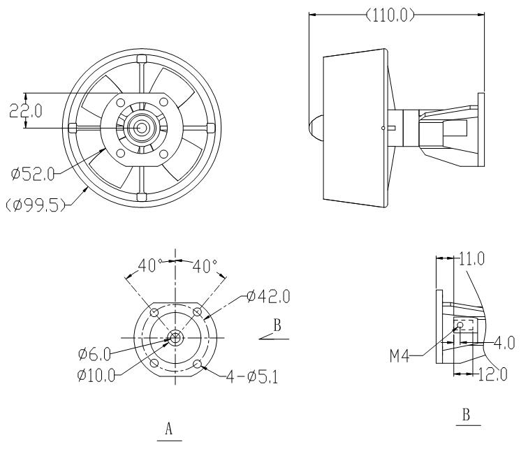
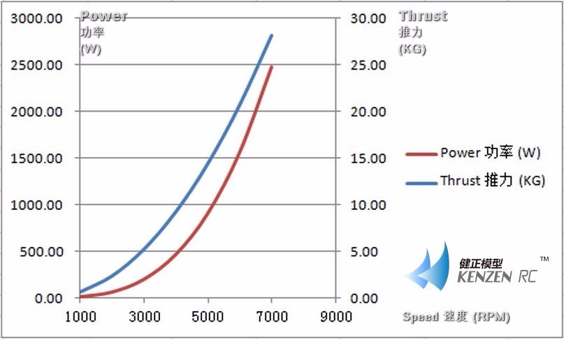
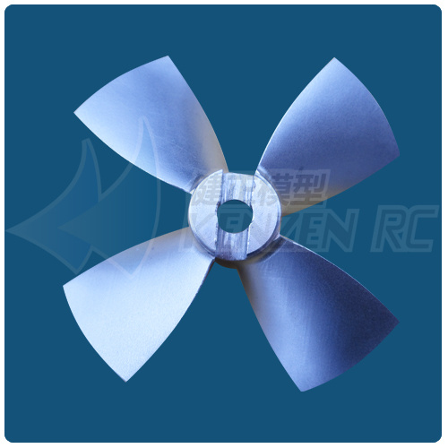
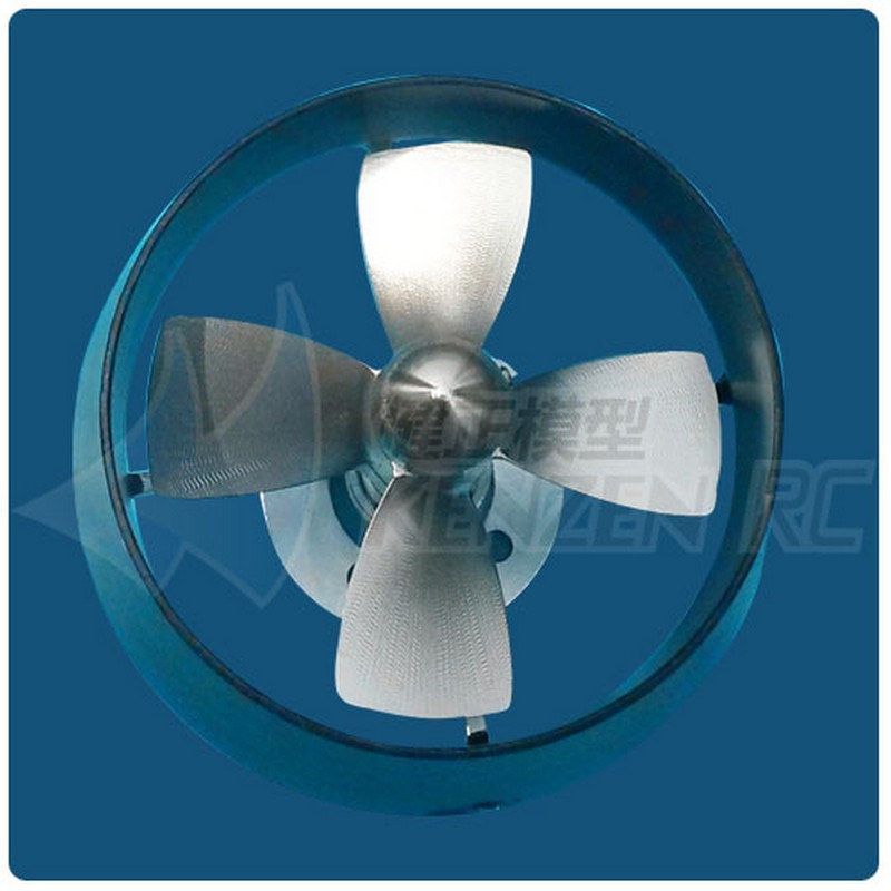
I’ve got the aliexpress kort of 80mm, however haven’t got a cahnce to test it. My plan is to test it with sss 360KV at 30v (vendor shows 27Kg of thrust). the kort has metal prop with think and narrow surfaces, which should work good at 7000-8000RPM below are pics of it. What do you think is 27Kg of thrust vs 2500Wt of power at 7500RPM - is it real?
Charlie, I like this idea. Even more compact and much less water. It could even have interchangeable test sections to accomodate different size propellers.
ps. Adding an adjustable flow restrictor somewhere in the loop would allow the operator to dial in the desired water velocity.
Very interested in your results for thrust with this 80mm assembly. We have this 80mm assembly with 0.8 pitch ratio, and the 1.2 pitch ratio. Using direct drive with SSS 500kv and 6S: 0.8 PR was 15kg, and 1.2PR, was 20kg.
You should get a little more torque motor torque with 360KV, but we found the SSS motor didnt have enough torque to get the prop turning at full RPM. We have since had a custom motor built which should pack 52% more torque than SSS model, and we have 250KV of this new motor coming and expect it to run 7500 - 8500 RPM under load.
Thanks for the data! I will post my results once will have some. @VeFoil do you have any feeling of current results on this 6s tests? how much power the motor was able to provide in this case?
This 250kv custom motor, can I buy it somewhere?
The motor will max out and draw its peak current and shaft torque (Nm) and then that’s it. Meaning, the SSS motor did not have enough torque to get the 80mm turning up to speed on 6S, and would not have any more power even if we used 12S. Volts regulate the RPMs mainly, not motor torque.
Typically a lower KV motor of the same diameter will weigh more because the windings are thinner, thus you can coil in more copper, and the more copper you have, the more torque you get. Which is why your 360KV will work slightly better than the SSS 500kv we used.
Yes, you can buy our VeFoil motors. We designed our motor to fit into 2.25" (57.15mm) aluminum tube, its 1+mm larger diameter and longer allowing two main things, a lot more torque, and much better thermal cooling with aluminum tube.
They are built for maximum power and to last in water with Stainless Steel motor case bolts, SS grub shell screws, and high-speed ceramic bearings for low heat, no maintenance, and rust free operation.
Once we finish testing the motor in a few weeks we can do custom KV to fit your needs, and the best part is we can get a motor built and delivered in about 20 days