Thanks for the answers guys ! One more question, With an outrunner, do we really get 7 or 5 times more torque than a 56 mm (or even 58 mm) inrunner ? because with inrunners you have to use a gearbox and it’s a ratio between 5 and 7. For a same power the outrunner have to turn 5 (or 7) times slower than the inrunner right ?
Outrunner does not have 5x or 7x the amount of torque as an inrunner. The torque production is a function of the torque moment arm length. This is far more significant the smaller a motor is because the slot length and back iron thickness of an inrunner motor are roughly constant (10mm - 20mm). The larger the motor becomes the less large the torque production gains are by moving to an outrunner design. Torque = r * F sin(theta), which can be simplified to r * F.
So for a 50mm OD motor the back iron thickness and slot depth account for 20% to 40% reduction in torque for the same given force production in the inrunner motor design configuration. If you have a 100mm OD motor then you will have a 10% to 20% reduction in torque when compared with the outrunner design. Now these numbers are all focused on torque production.
What they do not take into account is efficiency. Efficiency is what will effect the output power vs input power.
How is F calculated? What is the limiting thing? Is it magnetic flux density in the air gap?
Responded to wrong person - see below.
It is a function of the air gap flux density, efficiency, winding factor, EMF shape, electrical loading, rotor length, rotor diameter, magnet Br, BH information of the magnetic steel, etc… So there is actually a lot of information necessary for calculating torque production. The big take away is that you can only reasonably produce as much torque as you can dissipate heat. Outrunners in a sealed pod are far more difficult to cool than an inrunner design which may mean that the in runner can produce more torque solely because it can stay cooler.
An outrunner and also inrunner can be cooled by water running through the winding package. If you solve the cooling issue, what is the next limiting thing? Is it the flux density in the tooth or in the air gap?
Is F proportional to the surface of the air gap? Than torque would be proportional to the volume the air gap encloses. Torque would be proportional to radius^2*length of the rotor. This would explain the great difference in torque outrunners and inrunners can achieve. Because in praxis we see that outrunners deliver 2-3 times more torque than inrunners having the same weight.
If you just compare out and inrunners of same diameter, it is because the torque arm of the outrunners is longer, the magnets are about one radius from the axis, at inrunners you just got about half of the distance magnets-axis so half of the troquearm so F*torque arm = torque…so ~2x torque for outrunners at same diameter.
You are right in that the torque production increases with the ^2 of radius (radial direction) and torque increases linearly with added rotor length (axial direction).
I should mention that I have been using basic physics equations to try and better explain the relationship between rotor diameter/length and torque production. The next equation that better defines the relationship is
T = 2πr^2*ℓ < τ >
If you want to know more I recommend picking up James Hendershot’s book on brushless permanent magnet motor design.
Next limiting item would be saturation of the magnetic steels and/or risk of demagnetization due to too strong of a field (lots of air gap flux) and too high of a temperature or too high of airgap stress. It’s hard to tell because I am making generalizations about the motor design. Realistically these items would be individually addressed during a magnetic FEA.
Check out this paper:
Page 2 should have some of the information you are looking for.
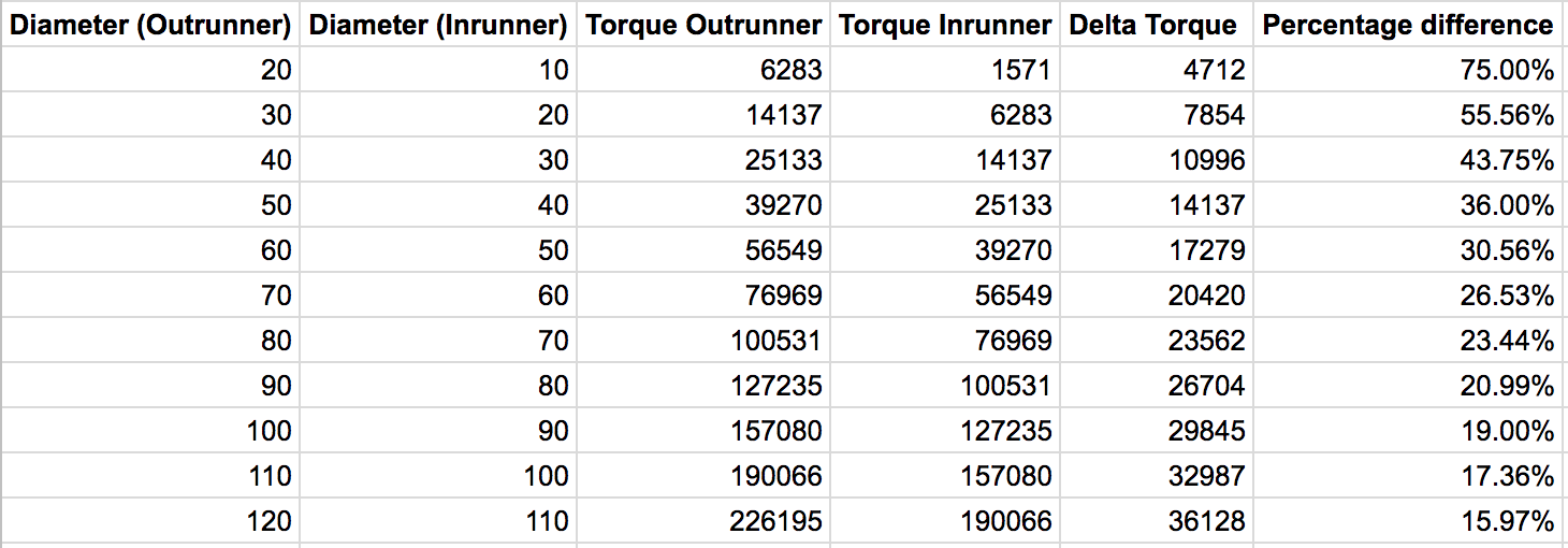
Example of how the difference in torque production of an inrunner vs outrunner becomes less significant the larger these motors become. At 60mm (outrunner) and 60mm inrunner OD the torque difference is approximately 30%. However at 20mm OD the outrunner produces 75% more torque.
2 Likes
So, lets see what the practical dimensions of the comparable motor classes tell us. Does anyone know the dimensions of the rotor in e.g. SSS motor or the tppower motor widely used in this forum?
E.g. for an outrunner we have the APS 6384 with 950g weight. Stator dimensions for 6384 is diameter 53x length 50mm = 110 ccm or even 53x55mm = 121ccm if optimized. For the latter one the weight might increase to 1050g. Than we might introduce some correction factor because the outer diameter of SSS and tppower is only 57-58mm. The table of Mr. Hendershot seems to be an incorrect simplification to me.
I have been simulating electrical motors with femme HomePage:Finite Element Method Magnetics and also built some outrunners using existing stator from industrial automotive fan. The results showed a deviation of 5-10% compared to the simulation. If someone provides the geometry of the stator and rotor and winding data of such inrunners i could simulate the standstill torque.
2 Likes
PowerGlider I’m dubious about shock from a battery source.
Normally electric shock happens because the AC voltage we get to our homes has it’s return path through the ground. Outside the house there is a stake in the gnd and neutral wire goes there. It’s cheaper.
So shock happens when your hand touches active wires, and your feet touch the ground, so completing the circuit. 50/60Hz AC is required for damage as this causes nerve damage and defibrillates the heart.
If you have a battery, the return has to be through the -ve terminal, so you can’t get a shock unless you are holding +ve and -ve together and are more conductive than salt water. So it takes two hands, *** a lot harder *** and there’s a nice salty conductor with infinite paths for flow and the low network resistance you get from that.
You’d really need to try very hard IMO. I would suggest it’s not possible.
There are questions about the frequency of the phase voltage, I don’t think >20khz will do much; there is a magic frequency where nerve cells aren’t affected, it’s something like 700hz but this might not be accurate, but it’s a ton lower than ESC drives. You have the heating effect, but that just bbq’s skin, big deal, get a bandaid.
1/kv is the torque constant. So the lower the kv the more torque. All this stuff - air gap flux density, winding factor, etc - is boiled down into torque constant.
Choose the motor with the lowest kv, that still has acceptable cross section & drag. Simple. I think everything else is academic.
Every setup has at least one gear box. It’s the prop and you can design it to spin fast, requiring less torque, from a direct drive.
Agree with the cooling comments, but I thought this thread was about sealing and cooling directly with seawater flow? I see the big issue as corrosion.
As we do not know the cross section of the windings and we can thermally overload the motors being cooled so well, it is not so academic. The problem is, if you have slightly wrong parameters given, it is not so dramatic, but if you use the wrong formula to decide between one or the other technology you end up with the wrong decision. So there is still some gap in knowledge, because there is so little data available for the inrunners used in this forum.
You are right about the return path, but remember, every part of your battery and ESC box and wiring needs to be isolated. A single fault e.g. inside your safety switch will close this return path, and regularly you will touch it with your left hand while standing in the water, cause your right hand holds the controller. So i suggest to have everything isolated by design, the motor windings and stator iron covered by epoxy and using IP68 rated plugs and so on, so you need a double failure to create any harm. Prove the absence of single failure by testing in salt water from time to time.
torque constant is important, but remember a 10mm OD motor and a 100mm OD motor can have the same KV and the same torque constant. However, one will be capable of producing more torque. So it is far more than just torque constant. You really need to know your airgap flux density, winding factor, and motor volumes to be able to estimate your torque production. The lamination saturations effect your motor efficiency which effects the continuous operating performance of your motor.
I think the motors either need to be modeled, someone needs to do a dyno test, or the suppliers need to be asked for speed/torque curves. This is really the only way that you can compare the actual performance differences. Additionally the motors need to be temp tested to determine their continuous operating point. Adequate cooling will make or break your E-foil system much more quickly than just choosing an inrunner design over an outrunner design or vice versa. Just make sure that the motors are sized properly for the application. Electric motor designers will typically start by doing a volumetric sizing of the motor for a given torque. This process is purely analytical and is a great tool to quickly determine the size of motor necessary for the application. From there the motor needs to be optimized to improve efficiency and reduce unwanted current harmonics and/or flux leakage due to poor lamination design. That is another problem with many of the hobby motor designs. The back iron thickness is often far too thin and the motors exhibit significant eddy current losses.
FEMM is a great tool, but as you said the wrong formula can lead to you choosing the wrong motor topology, so really if you have 10% or 15% discrepancy in your modeling then that is far too much to be useful for making a motor selection. To improve your model accuracy you probably need the BH curve for the magnets the supplier is using and a BH curve for the lamination steels. Additionally, there are other effects caused by stress in the steel laminations that is quite difficult to model. Realistically you will need to rely on supplier provided performance information or perform bench/dyno tests on the motors you are curious about testing.
“Every setup has at least one gear box. It’s the prop and you can design it to spin fast, requiring less torque, from a direct drive.” then I don’t see the point, the goal is to have a high enough torque so that we can put a bigger prop and have higher thrust. It’s more efficient this way. A direct drive with outrunner will also reduce cost if it’s easy to cool down and maintain. But if the outrunner doesn’t have enough torque for a direct drive, I don’t see the point of using it.
I wrote 5-10%, not 10-15%. The motor constants were almost correct, the deviations were about cogging torque. Also the question is, how exact the measurements are. E.g. the material of the rotor is not so easy to find.
So what was the inaccuracy? Were you comparing different torques at different speeds? or were you just looking at torque vs current? Or possibly comparing the current waveform of the FEMM model to the actual motor? What were you comparing on the actual motor to your theoretical motor? 5% - 10% accuracy without any information as to what it relates too is not very helpful. I personally have a lot of experience with using Infolyticas Motorsolve and Magnet software for designing brushless permanent magnet motors for industrial applications. My experience is limited to inrunner designs because outrunners are not commonly used in industrial applications although washing machines do frequently use them.
Maybe washing mashines have high price pressure. Its very easy to construct an outrunner. I wanted to point out, that 5-10% deviation between simulation and reality, using a 2D software is a good thing. I am fine with the accuracy i got.
Hey Climbineer, what do you think is the best motor (available in the market) for us ? To me it seems like a direct drive with outrunner is not suited for this application.