Just a suggestion with the batteries. If you’re after a long lasting ride, it would be better to go for a minimum of 20000mah
1 Like
Thanks for reply, I was also thinking of multistar 20000mah but now the most important part is “right” motor
1 Like
Lets try a simple approach. Start with your end velocity you want to reach, lets take 20km/h. You choose a voltage for the batteries. Lets take 48V.
Correct layout of propeller pitch suggested often is that you have around 25% slip. For very small propellers in a duct this can increase, so lets say 33% slip. I use a prop with 5.25" pitch.
By this you calculate the needed RPM/V=Kv for your motor.
v = V_bat * RPM / V * pitch * 0.66
For the 180Kv motor you get 48V * 180RPM / V * 5.25" * 0.66 = 8640 RPM * 0,088011m = 760 m / min = 45,6 km/h. OOops - that was way too high. You might never reach this velocity because the power demand might be higher than what your system can provide. If latter is true your system needs adaption somewhere.
Cutting down the voltage could be an option, but than you reduce power density in your motor linearly.
Using a lower pitch prop could be an option, but you loose efficiency and end up with very small props around 100mm i guess. On the other hand virus built his jet system with rather high efficiency, so you could give it a try.
So for best efficiency you should have a motor with 100Kv or less. If you doubt that an 6384 100Kv PowerGlider can handle your task, ask Bruno if he can deliver the 83110 WC with 50-90Kv.
But be careful with the watercooled versions: If you do not want to let it run with water through the windings, like i do, you get definitely worse cooling. You need an additional housing around the turning rotor and you need the sealings for the motor axle. All this adds drag and complexity. So another solution could be to use a 80100 with 80 or 50Kv and a larger prop and let run submerged with a pitch of 6-8".
If you want long distance, go for minimum 30Ah 12S.
All this is only an opinion based on some rough estimations and little experience.
6 Likes
thanks for the information. The open version is also possible because we want to ride it only in fresh water - river, lake, not salty sea water so water cooling through should be ok.
Hello! I looked through the page several times, but I can not find to what diameter you have turned the propeller. I came across a figure of 140mm, did you stop at it? I’m now adapting the propeller from the topic “Pacificmeister Build Info and CAD Sources” for use on the 6384 100Kv PowerGlider motor, but I can not decide on the diameter.
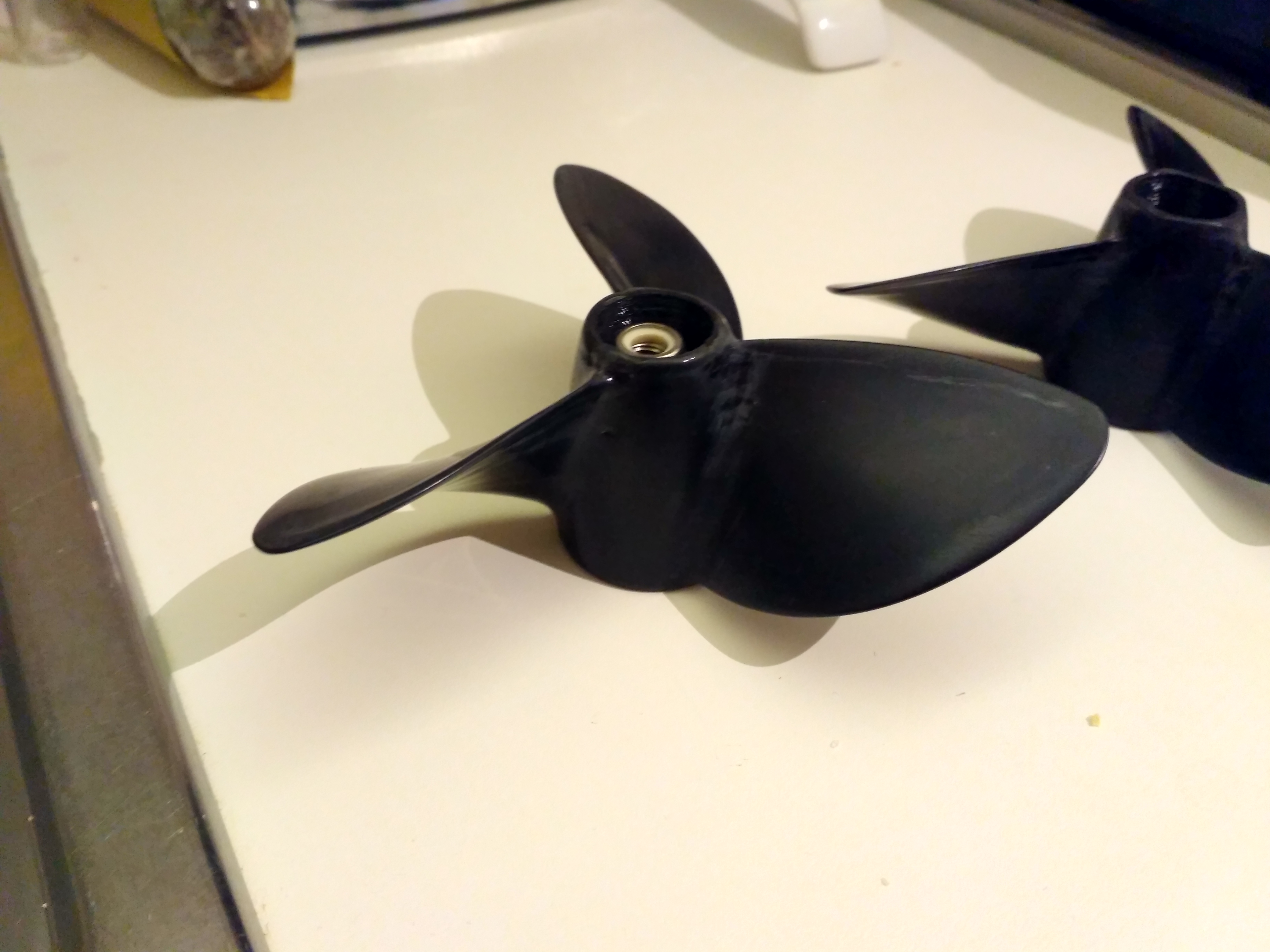
My duct has inner diameter of 140mm and i cut the prop further down to around 138mm.
I recommend to use commercial props at the moment, because nobody here in the forum was able to outperform them. Home Made Flume - #41 by PowerGlider - Props & Ducts - FOIL.zone
All the home made props suffer from low mechanical stability, which is very important for high efficiency so i decided to use something proven. You get a thrust of 20-30kg, which the blades must bear without deflecting too much. So if you print in 3D make sure you have thick blades at least at the hub in the blades roots and the cord at the hub should be very long.
My first design had 175mm diameter, but that was definitely too large for the 130Kv motor.
I was not able to test my new setup yet in water with prop, so many parts to build and my 3D printer is kidding me with failed prints.
1 Like
I do not like the idea of using an industrial propeller because of the fastening to the motor. Pacificmeister successfully uses the printed propellers, there are several ways to increase the strength:
- Proper preparation of the model for printing.
- Temperature treatment in the oven to eliminate internal stresses and build up the field connection.
- Processing with chemical solvents to improve the sintering of layers.
In the end, there is a method of casting aluminum in a burnt form printed on a 3D printer.
In any case, for me, while e-foil is an experiment, rather than a commercial project, so I’m interested in doing everything myself)))
I think you could do the job with 3d printed props, just use some rigid and resistant plastic. Polycarbonate works good (these two, 143mm diameter 200 and 260 pitch, epoxy coated), designed with Javaprop and “shaped” in SW.
At work we’ve a testing pool (for bow thrusters trials) and I tested ASA and PETG 110mm 5 blades prop up to 5K rpm, 35kg thrust force, no damage. Over 4K and something the 110mm give up to cavitation. Still have to test those two in photo with efoil but I guess they will hold the strain, they’re more rigid than PETG and even than ASAUploading…
1 Like
Those props look really nice, must have little to do with what java prop generated.
The quality of surface is very good at first glance.
The pitch is almost the double of the one i am using.
I think, that printing the aluminium prop with around 130mm pitch in PLA or whatever recommends a lot of support, especially with all the cutouts to adapt it to the motor.
But it really looks great, congrats!
I am also using epoxy to complement PLA, so far it is nice to work with, although not the perfect combination i guess. At least the PLA soaks some epoxy in and makes a better part together with less effort than casting epoxy.
Maybe i should use some glas fibers on the outside surface of the duct to make it stiffer and more durable against mechanical stress?
I prefer to use PLA for non rotating parts, the spinner is an expection, filled up with epoxy. I do not believe, that any printed plastic is as durable as marine aluminum, i do not want to regress in material selection too much.
Also, for other parts i use different materials like the fin, which is used and was shortened to be less harmful. Its made of high density glas fibers. What i find cheap and proven i give a try. Undogmatic.

I’ve no problem in sharing the iges or even the Solidworks file, could be helpful but not too straigforward to work with.
I start with a Javaprop project exported as .iges, then open it in SW, close the surface to make the blade a solid, then i divide the blade in 4 or 5 slices, from the root to the tip, in order to extract the naca profiles and orientation.
I build a loft with those and start to scale each profile, from the center or from Leading edge or tip, depends if i want to “slide” the profile up or down to shape the blade. DO NOT just move the profiles around or you mess up the “corkscrew” (sorry for my English…miss the term do describe that).
done the shape, it’s matter of replicate the blade 3 times, add a hub, refine the 3d and send it to the slicer! I spent probably 2 years (from time to time) to learn how to do a real prop, tried so many method and software but only on this forum, javaprop discussion etc, made me seeing the light!
As for PLA: PLA it’s a great material bexause of reliability, size precision etc, it’s rigid and offer strong inerterlayer bond, but it’s brittle and it deform easily with moderate heat (black prop left in sun, or in summer into your dark car). It does the same even when multi coated in epoxy or poliurethane paint… can you believe that by dropping a just ready prop, after having wet sanded itthe 3rd layer of epoxy (3000grit sandpaper), it breaks one blade at the tip?! Surely it could do.
Tried many surfboard FCS and Futures type surf fin, from PLA to 910Nylon to ASA and PETG, coated and not… ok for surfing (my modest past fourty shortboard style) not ok for kitewave,only ASA did the thing. The only material that keep up is Polycarbonate but it’s not as easy and always perfect as PLA, it costs 3 times, only two colors…It stress cracks if wet in acetone, oil, certain grease, Sikaflex or other silicone… I wish to test these props on water soon, as said, my files are your files, drop me your email in pm and I’ll pass you the files, just as sample.
5 Likes
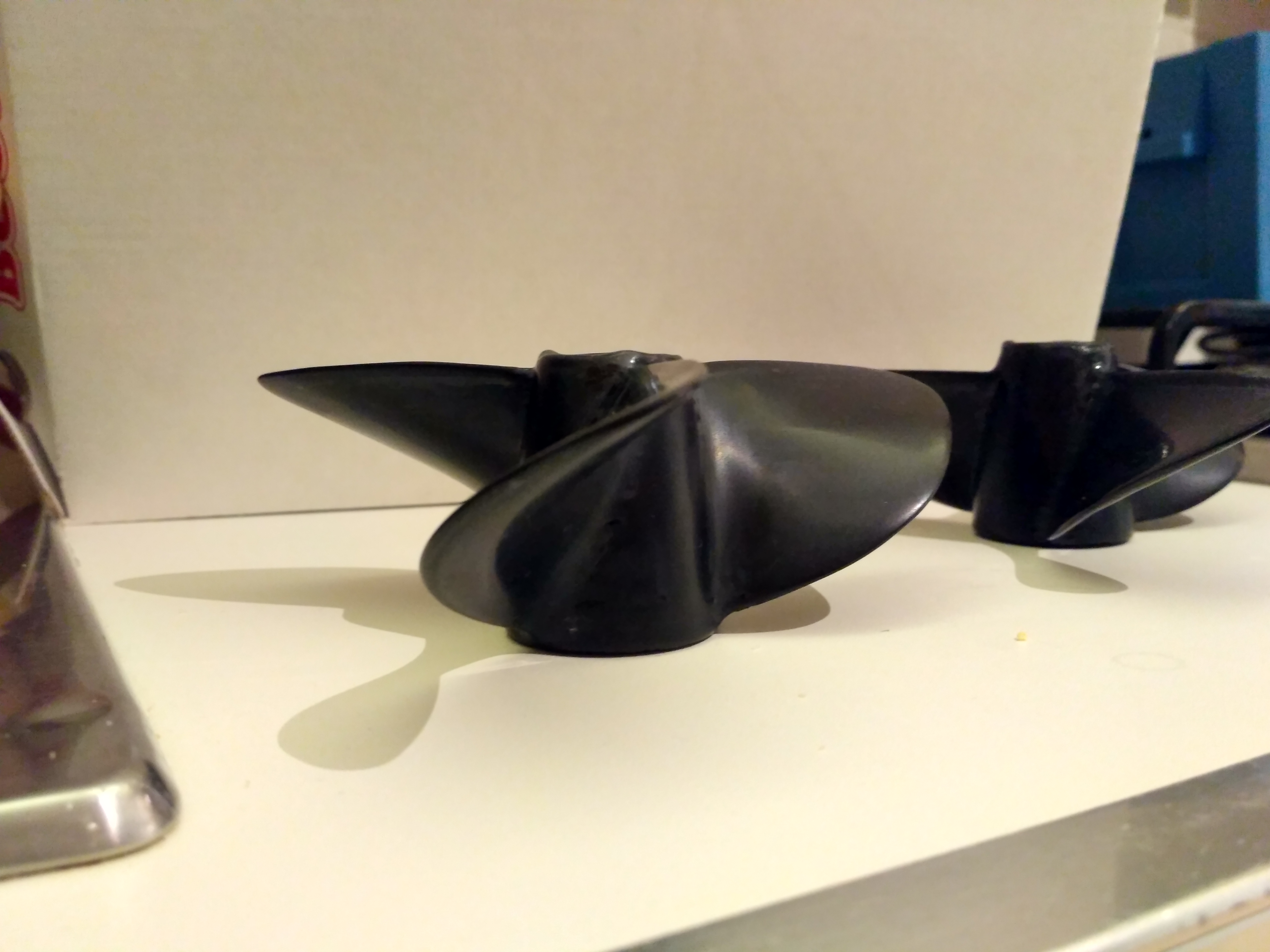
Very interesting, best source of information, thank you for telling your experience. I gave it up, because i can buy a rather well suited aluminium prop for 25-40€ and cut it down to my needs on the lathe. I am not sure if i want to change this in my design. Maybe if i experience i need a different pitch, but so far its fine and i built my system around this prop. Maybe we could design a new one and print it to test in watertank and then build a PLA hollow to sandcast aluminium with lost and burnt PLA. I have some ideas.
Today i made some progress with milling the glass fiber fin.
Has anyone tried this http://alienpowersystem.com/shop/brushless-motors/aps-70110-outrunner-brushless-motor-100kv-3200w/ ??
3200W is probably a little low considering Alien ahs a tendency to overstate specs, but looks like he made an outrunner motor inside a waterproof case that could be perfect for eFoils.
I don‘t see how this motor is cooled, otherwise a 7Nm motor for 120£ is good.
I am tempted to try this one. But I am very sceptical how the cooling is supposed to work. Maybe they put an outrunner inside and filled it with oil? That is my only explanation. I doubt they could build an inrunner at those specs and dimensions. If it is oil filled, we could let the oil run up and down the mast for additional cooling. My mast has two empty chanels inside. We could also elongate the motor tube for more cooling.
Hard to tell how this should work regarding the cooling and also the sealing. Material exchange is the most effective way of cooling, recirculating a gas is uncommon. On the other hand i see a niche for these encapsulated motors, as they are unique and for a minute they will last, maybe also 5 minutes is possible. You should have some temperature recognition. By measuring resistance of the windings or by a dedicated sensor within or nearby the winding or by a model. The magnets strength can suffer starting at 80-100°C.
These motor manufacturers come from the RC world, where air models are so overpowered you can believe a 1 minute full power sequence is always followed by an empty battery. You have the motor cooled by the downstream of the prop. With cooling the windings by water directly i contribute to the situation. The motor is under water, so how can i make the mass exchange to transfer heat so i can get 4kW from 1kg motor mass producing 30kg thrust at standstill? Where is your interface which has high thermal resistance? Eliminate it to get higher duration current capability and higher torque.
All these modern motors are made of high quality materials, available since decades, but now at affordable price. I built some motors for electric vehicle before using cheap base materials from automotive 850W blowers, there is a difference in material and design.
If you have new or better or other solutions to get the heat out of the windings, please let us know here.
I am trying to optimize it (to my feeled needs) in this thread with the help of you all, and even if i am not answering directly often, i read your posts and think over them. Thanks
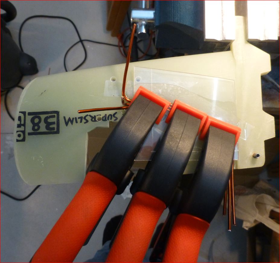
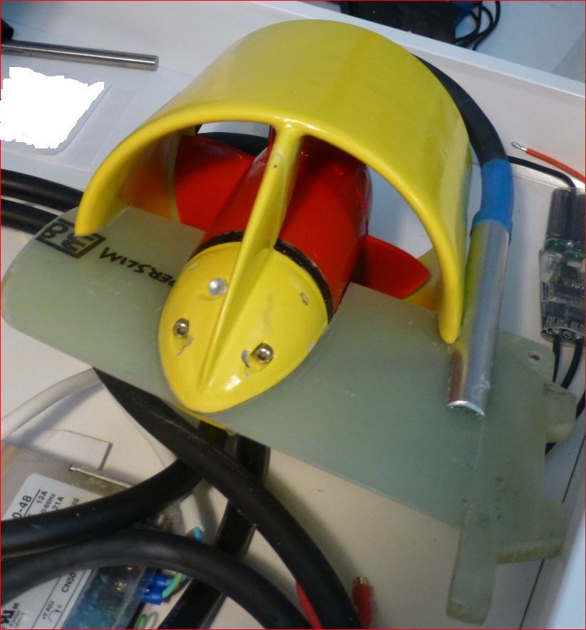
So here are some updates of my direct drive direct cool build:
Find the innovation!
I found a way to balance this prop together with motor:
I use a single ball bearing without thightenings, removed the grease with ethanol, oiled it again to make it run a smooth as possible. I am lucky i can support the motorpropspinner in its center of gravity. I use an original motor hub for this and put a single very long M4 screw into the back plate and clamp this in a bench vice.
Beneath this stands a bench grinder with some inbalance. If i run it, the motorpropspinner will start to vibrate slightly and move the balls in the bearing, diminuishing the friction in the bearing and the motor will swing in like a pendulum. You can add or substract weight. Time consuming and in the end its not perfect, at least its much better.
4 Likes
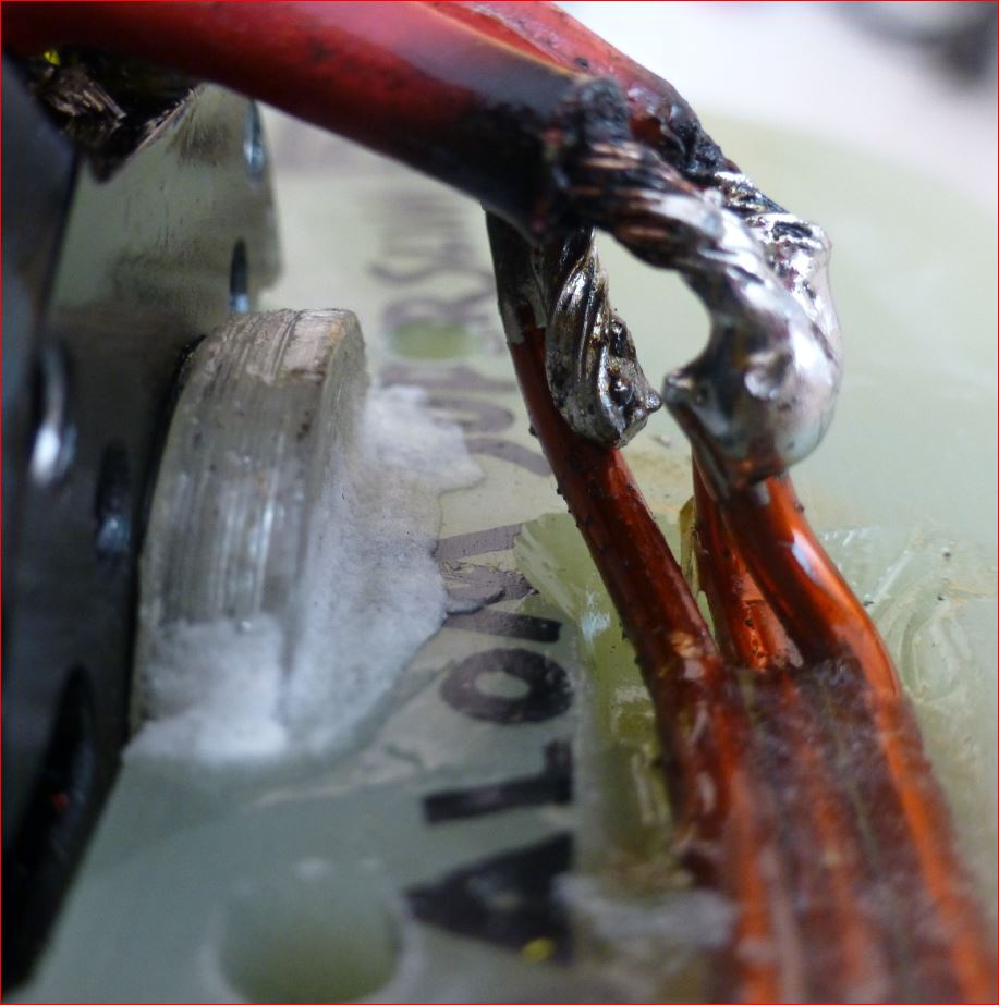
So I guess it would be wise to have the cables submerged in water too. I am designing a similar motor pod but with water flowing through the nose cone. Not sure if the mast attachment is the best idea anyway. Pacificmeister did a prototype where it gets attached to the fuselage. Why not mou t it right in front of the front wing?
The red parts turn, the others not. I made this cutout in the fin to get a good design, where everything is intersecting saving a lot of space and at the same time providing support, some degree of protection for/from the prop, and a low drag. Flipping the motor into forward direction could work as well if you want to underride patent but has some drawbacks as you loose the mast as a part of protection. I think this design can be adapted to foil and mast easily. Make a longer nose cone so the cutout in the mast gets small or vanishes, put a prolonged tunnel over it.
One could also integrate the foil, mast, part of fuselage, motor holder and motor into one part, to come over the simplistic approach of modules.
Development could also end up with lots of modules stacked at the mast, like Doppeldecker foil surrounding the motor(s).
Who knows. For the moment i have this design, lets see what it can do. The old one is also in good shape, i can compare them maybe.
I plan to test in Hyeres starting end of month.
P.S. Did you find the innovation visible in the two pictures?
2 Likes
P.S. Did you find the innovation visible in the two pictures?
Not really.
1 Like