Could anyone with Reisenauer chief + flange provide all dimensions please?

I would like to make an STL, 3d print it, and just test screw fittings etc…

Or maybe one already exists somewhere ? Not at Reisenauer’s…

*** Edited : I thought I found a good price in the US but that is the Micro edition, not the chief nor the super chief

This is micro , not good , super might work ( nowone has tried it yet, chief ( the biggest) work well

What exactly do you want to print? At the position of the flange nothing has to be printed, only at the gearbox output. And for that different CADs are available in the forum, depending on how the rear part of the propulsion unit is designed, different solutions exist. Just search for “Reisenauer”.

Just like I wrote. I want to 3D print the chief and the flange at scale 1:1 and no, there are no Reisenauer CAD on this forum - that I am aware of (I have been on the forum from day 1 but I may have missed a thread ) nor on the Reisenauer site…

1 Like

Some excellent info here

*** Gear reduction 4:1 = 12,1mm, 5:1 = 9,47mm, 6:1 = 8 mm, 7:1 = 6,61mm, 8:1 = 5,8mm

*** The correct distance between the motor pinion toothing to the flange thread is 1,5mm (+/-0,5).

*** diameter 38,5mm – length: 27mm (without shaft and flange to frame pad) output shaft: 6x7 (one part:
shaft and planet carrier)

*** Maximum immersion depth of the 3 front fixing screws = 8mm

*** Bolt circle 30mm, M4

*** Federal 21.6mm
What the heck is a “federal” ?

1 Like

Now I understand what you want. At Reisenauer’s page it says the PDF for the Motor Chief will be added soon, so you could ask them about it.
“Federal” is a translation error, it says “Bund” in German, but as I also don’t know what this is referring to on the gearbox, I can’t give an exact translation either. But I think “collar” goes in the right direction. It is definitely something round.

Federal in the first diameter before the bolts , the hole you have to drill in order to hold the gearbox after the propeller by the 3 screws
It refers to the "motor holder " section

1 Like

Interesting Alexandre, thank you.

Here is what I need please :slight_smile:

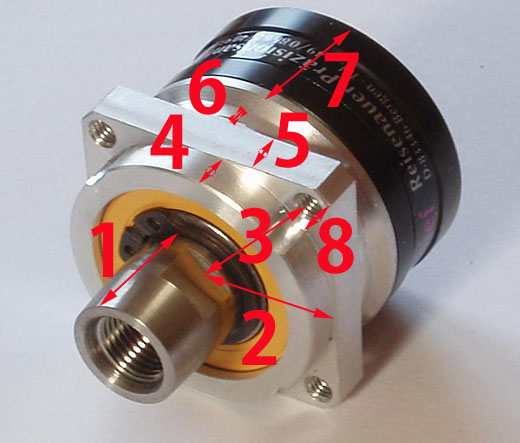
1 length and radius of shaft fitting (or whatever it is called)
2 radius of the first metal “cylinder” (is that 19.5 mm ?)
3 radius to the bolt center (15 mm, right Alexandre) ?
4 first metal cylinder thickness
5 Square metal thickness
6 second cylinder thickness
7 base cylinder thickness
8 Bolt radius -M4 -> 2 mm

I understand that 4 + 5 + 6 + 7 = 27 mm

Thank you :slight_smile:

reisenauer

1 Like

in my head i have:
1 : 15-18mm? with diameter 15mm
4: 4-5mm
5: 5mm
6+7: ±22mm
8: m4
overall front diameter 35mm
overall square diameter 47mm

1 Like

Merci Alexandre , nice from you !

I can’t figure out from your llast number though.

entraxe de trous m4 en diagonale :47mm or 41mm don’t remenber

2: ( 35-15)/2
3: (47 (41) -15)/2

1 Like