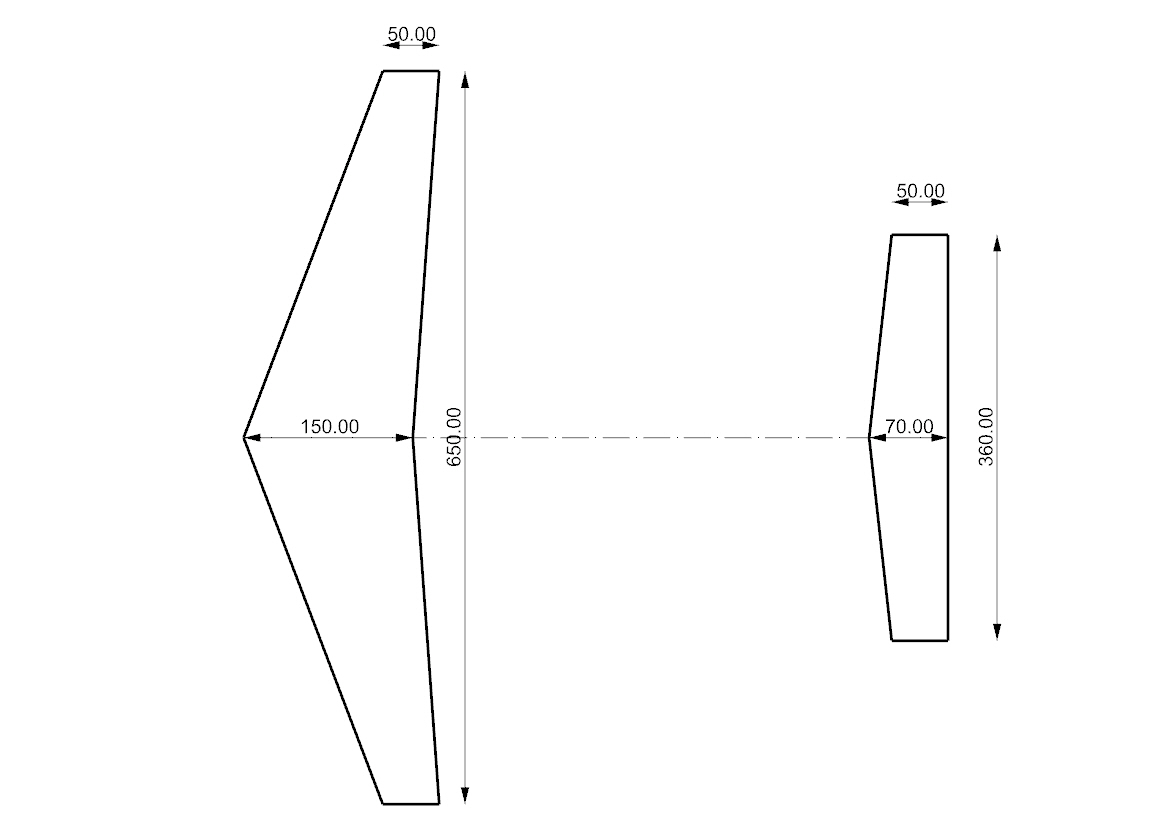
Second iteration 250mm half wing, 150 root chord, 50mm tip
These are half wing numbers, be sure to double the lfit, drag and watts numbers for a full wing.

3 Likes
Yes, I am also a proponent of a larger wing and a greater distance between front rear. U Kite Foil helps the dragon itself drag the sliders up
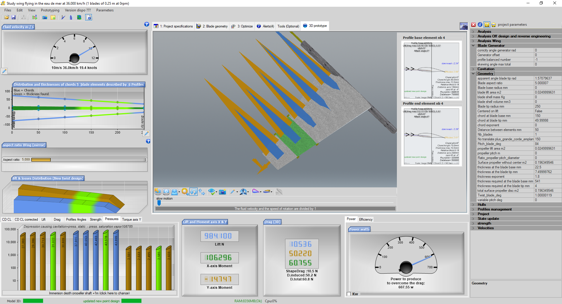
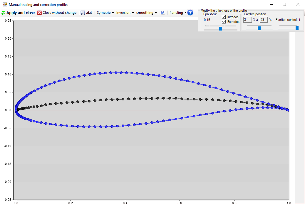
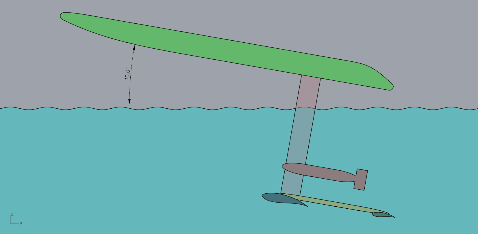
some software simulation explorations with variations of attack angles and the effect on lift. This is the base configuration.
The goal would be to get up on foil at as low a speed as possible, yet when at a high speed have reduced lift and reduced drag. This increased angle would be controlled by the inclination of the board itself, nose up angle more lift, full cruising speed, horizontal, controlled amount of lift. Ten degrees seems like a maximum.
NACA profile 632615 suggested by Clarin.
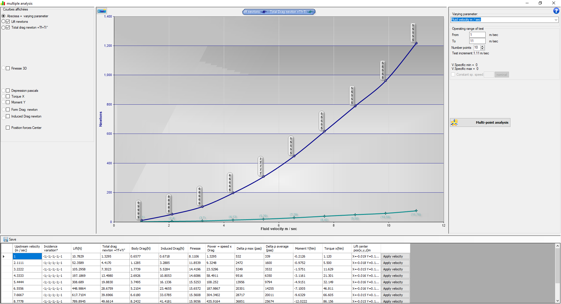
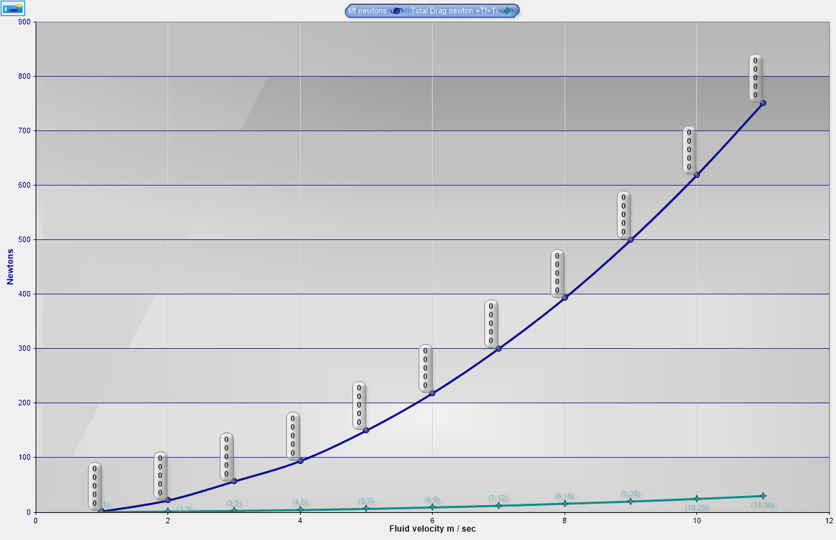
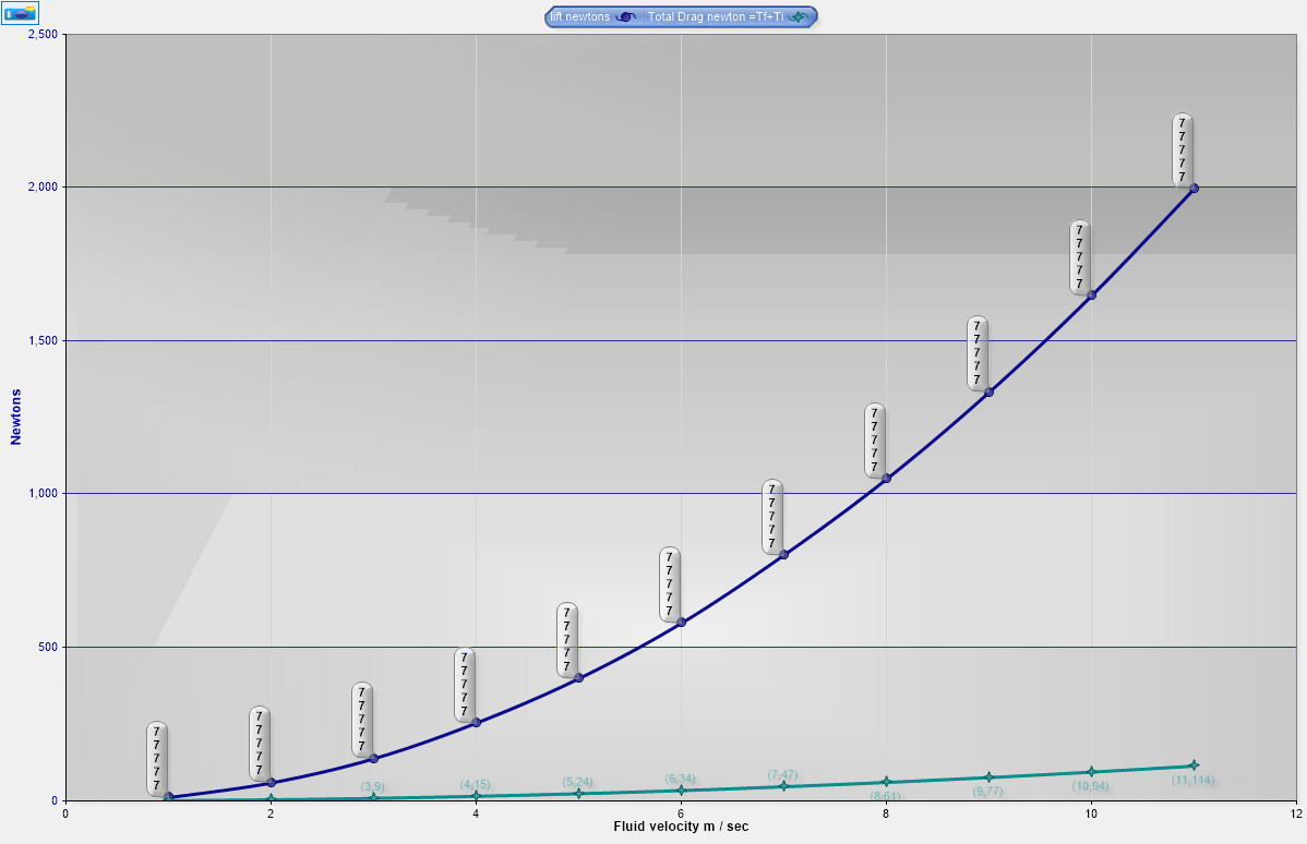
0 degrees, lift and drag in Newtons for a half wing (double values for full front foil)
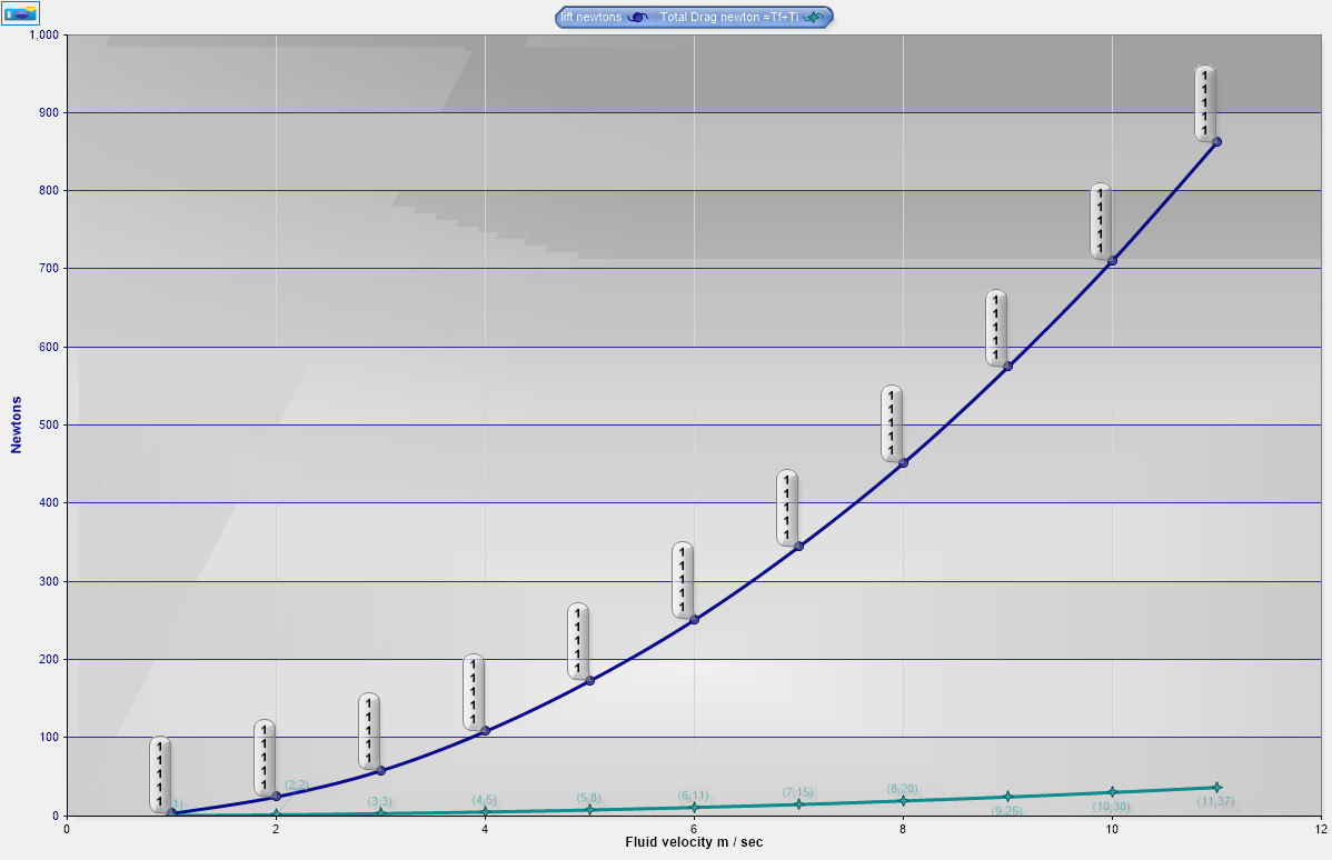
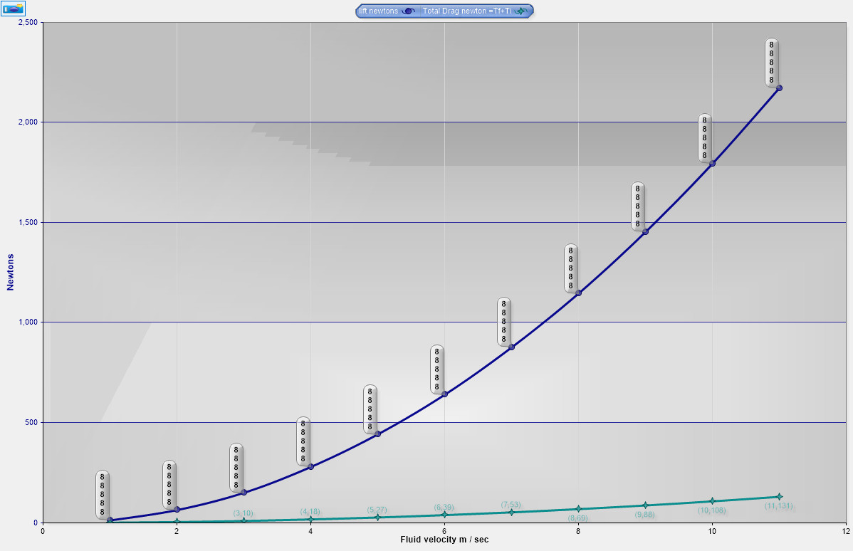
1 degree, lift and drag in Newtons for a half wing (double values for full front foil)
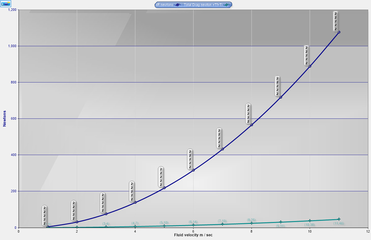
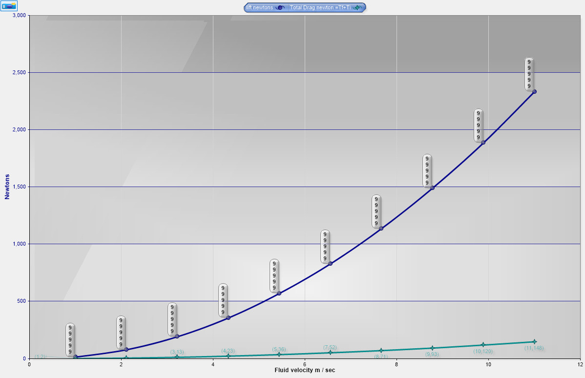
2 degrees, lift and drag in Newtons for a half wing (double values for full front foil)
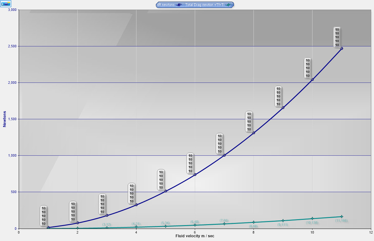
3 degrees, lift and drag in Newtons for a half wing (double values for full front foil)
4 degrees, lift and drag in Newtons for a half wing (double values for full front foil)
5 degrees
6 degrees
7 degrees
8 degrees
9 degrees
10 degrees
The preliminary analysis of the tail showed 39% of the front foil lift. The following table converts the Newtons to kiograms, doubles the values, and adds the tail values for a total lift in kilos at the various angles of attack and meters per second. Values under 150 kilos are colored blue, values above, yellow.
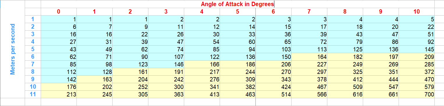
It seems like the range of lift can be controlled by board inclination, now to try more foil shapes and sizes and aim for more lift at lower speed, and less lift at 0 degrees.
5 Likes
Great info thanks! Do you think we could add some twist on the last 10-15cm of the foil? This would give more lift at lower speed and as speed increases the twist would “flatten” due to the flexion of the foil.
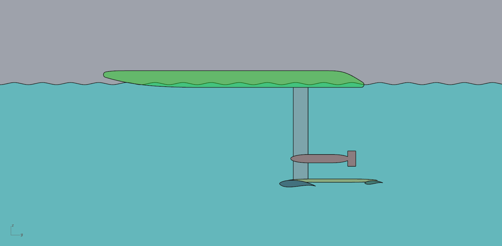
As my understanding of simulating foil characteristics in software expands. The effect of attack angle factors in, more attack angle at lower speeds give more lift. Many foils do not have increased drag at these lower angles, but the advantage of flattening out the angle at speed reduces the excessive overall lift. Some diagrams.
0 degrees sitting in the water.
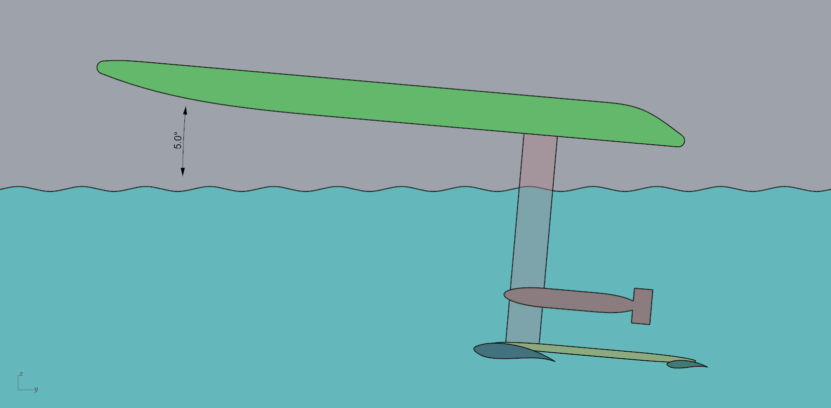
5 degree as kneeling starter position, could be more, the foil angle has also naturally increased.
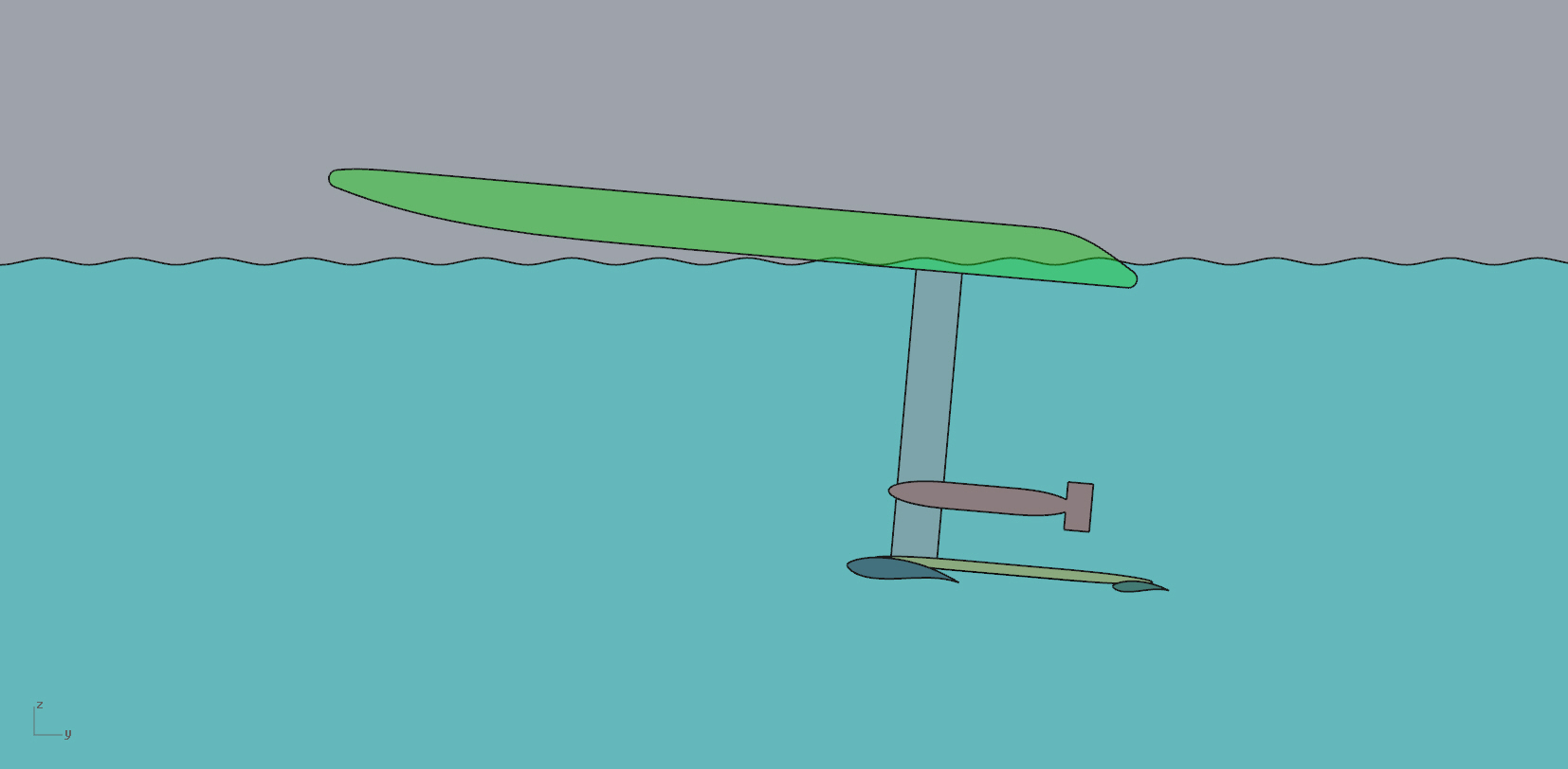
5 degrees
10 degrees
Hy, I didn`t get with what reynolds numbers you are calculating in the program?
Yes 11° pitch is possible with the right profile and makes it much more stable during landing and Lifft off;-)
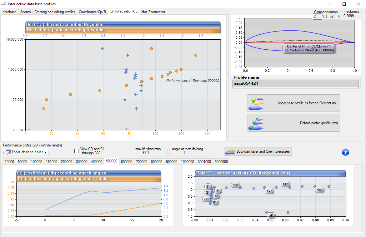
Using the program suggested defaults currently. the program calculates Reynolds numbers from 10,000 to 5,000,000 or allow a specific number to be input. This is an example of the foil selection dialog Reynolds section.
My understanding of Reynolds number is far from complete.
Hi I am Kalle from Finland. We ( my 5 friends) have build running efoil, but we have no simulation back round for the foils and propulsion. I have done rough calculations with basic physics. Can you help us to verify our foil and duct/prop calculations? We are looking after better foil and prop combination.
This is our foil gliding on cold (+6°C) the Baltic Sea last month.
https://www.youtube.com/results?search_query=e+foil+on+cold+baltic+sea
kalle & others
4 Likes
You should concentrate your calculations on Reynolds Numbers below 500000 
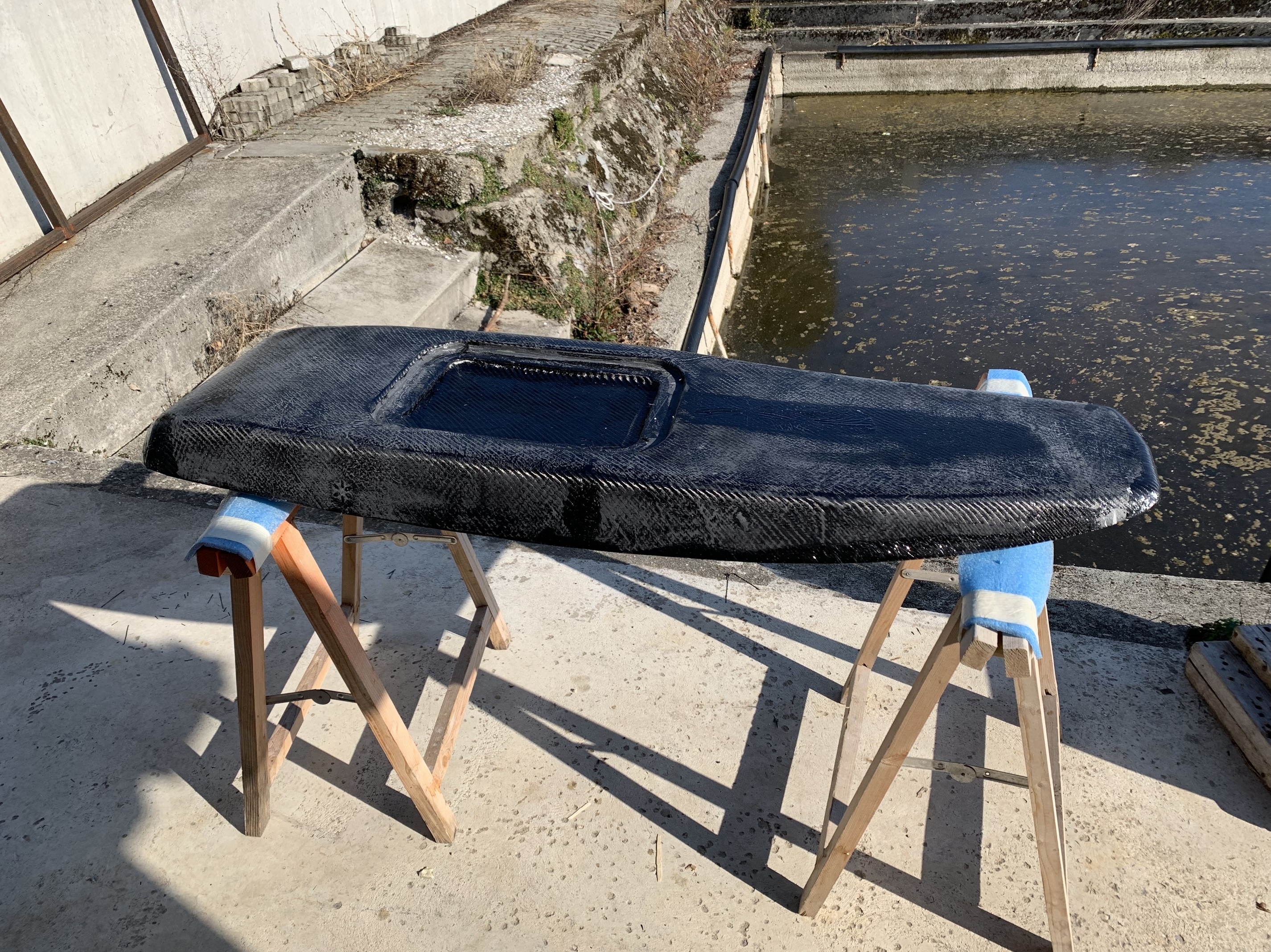
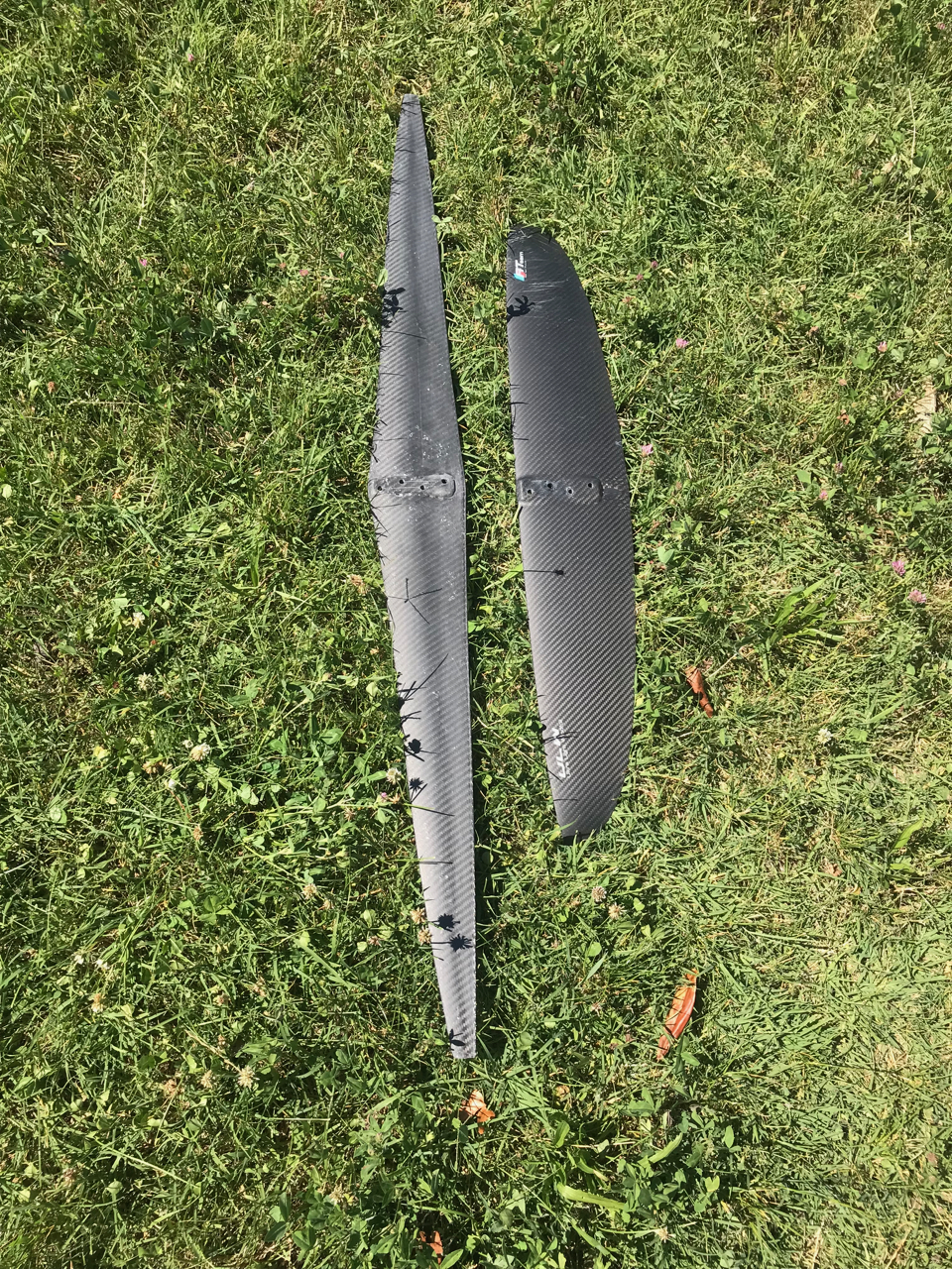
The last few weeks I have build a new front wing, it’s 900cm2 and 125cm wide the tip chord is only 2cm.
It really looks like a bad ass slicer, sadly it’s almost impossible to ride!
The roll stability is so hard to control, it balances from right to left and I can’t fly centred. The takeoff speed is about 9knots which is one knots better than my Alpinefoil ULW900 both have 900cm2 (the shorter foil on the photo)
The foil center of gravity turned out to be about 20mm more forward, maybe, this is the reason of the roll instability or maybe I will need to change the rear wing?

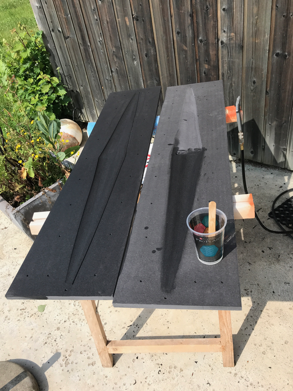
The molds been covered with epoxy
4 Likes
Awesome job, how was efficiency? Would not like to fall on that tip tho:p
Beautiful massive wing!
Do you know if it bends under load? Dihedral on a front wing is terrible for our type of hydrofoil control.
If my theory is right, then you might still be able to use it. Try to give it a serious amount of anhedral. You probably need to cut off the wingtips 30% of the way from the center. Then carefully glue them on at an angle so that the middle of the wing is around 13cm higher than the wingtips. (wrap the joints in carbon fiber to get strength).
I expect it to become usable that way.
Dihedral on the rear wing could help, but I doubt you will get enough roll-yaw coupling from a small rear wing when the main wing is so wide.
I have about 3cm dihedral under load, I always thought that the anhedral was useful in kitefoiling for the tip not to break the surface to often.
I’ll give it a go, thanks for the suggestion
My suggestion:
What we should do for the optimum profile is:
-Determine a take off speed
-Determine a maximum speed.
Without these circumstances given, It is impossible to create one.
My suggestions are:
8 mph for the takeoff
15 mph for the maximum
With these given numbers, a profile can be worked on for better results, I am capable of making the flow analysis by coding on my own.
The results would be better than ever, using those public software would never supply the true result. Even if you guys use the best ones ever, It will not be capable of getting a result with less than 20% error. (I am not mentioning the ones that the ones where their experiments are already done)
I would say I am rather more interested in creating a profile that is optimized.
My thesis topic will be a 2 flow phase analysis, where the foil is optimized by steps. So each time the analysis realizes the hydrofoil is not optimized, the system will iterate itself with different coordinates, which would make an impact on creating the best one.
In case one uses more lift than needed an unwanted drag would be inevitable.
4 Likes
@ christoff
I don`t know on what knowledge your front wing suggestion is based on…but maybe you should think about it again and see on what logical fact this is based on…
@Giga I’m sorry to tell you you’re not exactly right because you’re not taking into account that our hydrofoils are weight shift controlled flying objects and not “ordinary” planes.
@MaxMaker your intuition was right and has been proven with kitefoils.
Planes are not kitefoils and eFoils are not kitefoils. Kitefoils need an edge wereas eFoils are riding flat.
You don’t need a stabilizer to make a hydrofoil fly. That is pitch unstable but works
There are 3 ways to make a plane fly.
- traditional: positive lift front wing with negative lift stabiliser (rear wing) [UDL standing for Up Down Lift]
- tandem : positive positive (flying flea project circa 1930s) [Up Up Lift or UUL for short]
- canard (stabiliser fore = positive lift) main wing = positive lift
There is a path to investigate with stabilisers (rear W) providing a positive lift. Gong experimented this setup with their “Hellvator” kitefoils in 2016, based on a tandem setup.
-
Advantages:
1 - The total surface increases and don’t sustract: instead of having , say 700cm2 +(-300)cm2, the total surface becomes 700 + (+300), so you can have a foil with 350 front and 150 rear with same lift as a +800 - 300
The drag of the front wing is therefore divided by 2 whereas the drag of the stab is also decreased.
2 - The stability increases tremendously under 20 knots especially if the rider maintains his/her CG in the first half of the plane. From 25knots, the plane becomes more pitch unstable. -
Drawbacks:
D1 - the neutral point (NP) of the plane is moved aft by 10/15 cm. (the point around which the plane rotates in flight). The rider position instead of being fore the plate becomes aft the plate, ie more towards the plane tail. The best compromise would be to move the plate 15cm more aft to keep rider position at 25% of board length. But you are under the electric box on new board designs with no to not enough thickness.
D2 - At 30 knots, the balance becomes uncertain and very pitch dependent.
As a conclusion I would say that up to 25 knots, the tandem setup is very beginner friendly and should decrease the power consumption significantly. What do we want more ?
As a start, the process is to flip bottom up the stab of an existing kitefoil, Nobile-like 600cm2 Fwing and with negative lift stabiliser. It’s not easy as a 0 to +1 degree angle has to be found and maintained. This should give the same take-off speed as a 1000 cm2 supfoil with neg lift stabilizer with same or better longitudinal stability.
1 Like
While reaching for an ‘optimum’ wing design for a given set of speed/lift/handling requirements is a worthy task, you will most likely end up somewhere in the middle of performance for all parameters.
An alternative approach I’ve been considering is a ‘second wing’; smaller, high lift at slow speed and located towards the mast top.
The principal obviously being to raise the board out of the water as quickly as possible at slow speed, whilst also being clear of the water at higher speeds leaving just the main foil configured for higher speed use.
5 Likes
From this:
re number are around 600K at 5m/s (@11mph @18kph) and 200mm chord lenght this is LOW!. From my short experience, at this low re things go better increasing chord than span. Thin profiles work better than tick, of course this is hindered by structural concerns. Also i saw some foils with very blunt trailing edges :(.
Reading this topic with full interest!
regards
rck
Very nice piece of work.
What is the material in which you CNC’ed the molds ? Quite a few RC guys use polyurethane blocks.
Did you manage to improve the wing behaviour ?
If you stack up 2 layers of your black material, you could CNC a thicker mold with anhedral.
 for now I am building a new board.